
User`s guide

2 General Power Meter Functions
68 N1913/1914A EPM Series Power Meters User’s Guide
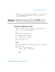
Combined Measurement
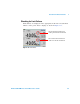
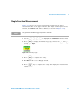
Figure 2- 29 shows a Combined Measurement configuration; Channel A and
Channel C to be displayed in the upper measurement line of the upper
display window. (For single channel power meter, N1913A, the Channel
field will be disabled, as shown in Figure 2- 29).
Figure 2-29 Measurement Setup showing combined configuration
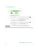
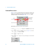
1 Use the , , , , to highlight the Combination function field.
2 Press to display the Function pop- up (see Figure 2- 28) and use
the and to highlight Combined.
3 Press to complete the entry.
4 Press key to complete the setup and display the measurements
results.
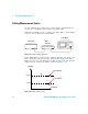
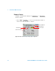
Figure 2-30 Measurement example display
Selected window/
Function field
Gate fields
Measurement fields
Combination field
measurement
Channel fields