
Operating instructions


University of Saskatchewan
Electrical Engineering Laboratory Equipment Manual
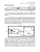
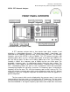
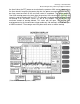
The display of the analyzer may be set to start or center modes, as indicated by
the switch with STR and CTR above it. Depending on this switch, the LED display
indicates either the start frequency in Hz, corresponding to the leftmost line on the
display, or the center frequency in Hz, corresponding to the center line on the display.
The adjust knobs (coarse/fine) to the right of the LED display control the start/center
frequency. Not all of the HP 3580As have this LED readout; some have an analog
start/center frequency readout. It doesn’t matter what type you choose, as they both
work equally well.
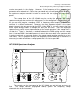
The SWEEP MODE dial should be set to REP (repetitive). At no point in the labs
will you need to set the mode to anything but repetitive. The remaining three dials,
RESOLUTION BANDWIDTH, FREQ SPAN/DIV, and SWEEP TIME/DIV all work in
conjunction. As was mentioned earlier, selecting a narrow RBW will yield a more
accurate spectrum, but the sweep speed will need to be slowed in order to maintain an
accurate reading. If your selected sweep speed is too fast to maintain an accurate
reading, the ADJUST indicator will light. Adjust the sweep speed to a slower value until
the ADJUST indicator turns off. At that point, the display will be accurate.
The RESOLUTION BANDWIDTH dial has another control, DISPLAY
SMOOTHING built into its knob. This control has three settings, and should be rotated
fully counterclockwise to its minimum position. Display smoothing is also known as the
video bandwidth on modern analyzers, and is, as the name suggests, a control that
adjusts the smoothness of the displayed spectrum. You may think that the display
smoothing should be set to its maximum setting all the time, but like the other frequency
sweep controls, it also is tied into the sweep speed. At its maximum setting, the sweep
speed must be set prohibitively slow to ensure an accurate display.
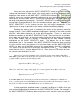
The amplitude controls are found along the bottom of the instrument. The
analyzer has two vertical display modes: linear and logarithmic. These modes are
selected by the
AMPLITUDE MODE
pushbuttons found
just to the right of
the power switch.
The UNCAL indicator light found to the right of the INPUT SENSITIVITY knob will
light when the CAL adjust knob is not rotated fully clockwise. This means that the
display of the analyzer is uncalibrated, and therefore inaccurate. Always rotate the CAL
knob fully clockwise so that the UNCAL indicator stays off.
Before ever connecting an input signal to the analyzer, always adjust the INPUT
SENSITIVITY control to its least sensitive setting. This means the fully
counterclockwise position, minus one. The fully counterclockwise position is the CAL
(calibrate) mode. This mode disconnects the front panel inputs from the analyzer, and
internally connects a 10 kHz calibration signal, obviously for calibration purposes. This
mode will be explained in detail later.
LIN
10 dB
1 dB
LINEAR
LOG
dB / DIV
ON (AC)
OFF
ON (BAT)
CHARGE
dBv / LIN
dBm
600
CAL
10 kHz
NORMAL
CAL
MAX
INPUT
OVERLOAD
UNCAL
VERNIER
(CASE GROUND)
POWER AMPLITUDE MODE AMPLITUDE REF LEVEL INPUT SENSITIVITY INPUT