
Service manual


RS-232-C
Configuration
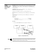
At power up, the RS-232-C interface is configured as shown in previous figure. To
change the RS-232-C configuration:
1. Press the I/O key on the front-panel keypad and the I/O menu will appear on
screen.
2. Rotate the KNOB until "I/O Port Configuration" is highlighted.
3. Touch the SELECT key and the External I/O Port Configuration menu will
appear on screen.
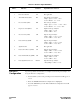
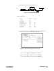
RS-232-C
Pin No. Function Standard Signal Direction and Level
1 Protective Ground AA Not applicable
2 Transmitted Data (TD) BA Data from Logic Analyzer
High = Space = "0" = +12 V
Low = Mark = "1" = -12 V
3 Received Data (RD) BB Data to Logic Analyzer
High = Space = "0" = +3 V to +25 V
Low = Mark = "1" = -3 V to -25 V
4 Request to Send (RTS) CA Signal from Logic Analyzer
High = ON = + 12 V
Low = OFF = -12 V
5 Clear to Send (CTS) CB Signal to Logic Analyzer
High = ON = + 3 V to + 12 V
Low = OFF = -3 V to -25 V
6 Data Set Ready (DSR) CC Signal to Logic Analyzer
High = ON = + 3 V to + 25 V
Low = OFF = -3 V to -25 V
7 Signal Ground AB Not applicable
8 Data Carrier Detect (DCD) CF Signal to Logic Analyzer
High = ON = + 3 V to + 25 V
Low = OFF = -3 V to -25 V
20 Data Terminal Ready (DTR) CD Signal from Logic Analyzer
High = ON = + 12 V
Low = OFF = -12 V
23 Data Signal Rate Selector CH/CI Signal from Logic Analyer
Always High = ON = + 12 V
Table 2-1. RS-232-C Signal Definitions
Installation HP 1650B/1651B
2-8 Service Manual