USER’S GUIDE AGILENT 6010A, 6011A, 6012B, 6015A, 6023A and 6028A DC AUTORANGING POWER SUPPLY Agilent Part Number 5964-8120 Microfiche Part No.
CERTIFICATION Agilent Technologies certifies that this product met its published specifications at time of shipment from the factory. Agilent Technologies further certifies that its calibration measurements are traceable to the United States National Bureau of Standards, to the extent allowed by the Bureau’s calibration facility, and to the calibration facilities of other International Standards Organization members.
Safety Summary The following general safety precautions must be observed during all phases of operation of this instrument. Failure to comply with these precautions or with specific warnings elsewhere in this manual violates safety standards of design, manufacture, and intended use of the instrument. Agilent Technologies assumes no liability for the customer’s failure to comply with these requirements. GENERAL This product is a Safety Class 1 instrument (provided with a protective earth terminal).
SAFETY SYMBOLS Direct current Alternating current Both direct and alternating current Three-phase alternating current Earth (ground) terminal Protective earth (ground) terminal Frame or chassis terminal Terminal is at earth potential. Used for measurement and control circuits designed to be operated with one terminal at earth potential.
DECLARATION OF CONFORMITY According to ISO/IEC Guide 22 and CEN/CENELEC EN 45014 Manufacturer’s Name and Address Responsible Party Agilent Technologies, Inc. 550 Clark Drive, Suite 101 Budd Lake, New Jersey 07828 USA Alternate Manufacturing Site Agilent Technologies (Malaysia) Sdn.
Acoustic Noise Statement Herstellerbescheinigung Diese Information steht im Zusammenhang mit den Anforderungen der Maschinenlärminformationsverordnung vom 18 Januar 1991. * Schalldruckpegel Lp < 70 dB(A) * Am Arbeitsplatz * Normaler Betrieb * Nach DIN 45635 T. 19 (Typprüfung) Manufacturer’s Declaration This statement is provided to comply with the requirements of the German Sound Emission Directive, from 18 January 1991. This product has a sound pressure emission (at the operator position) < 70 dB.
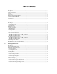
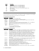
Table Of Contents 1. General Information Introduction .................................................................................................................................................... 9 Description ...................................................................................................................................................... 9 Safety Considerations .......................................................................................................................
Multiple-Supply Operation............................................................................................................................ 39 Auto-Parallel Operation .............................................................................................................................. 39 Series Operation .......................................................................................................................................... 40 Monitor Signals...............................
1 General Information Introduction This manual contains specifications, installation instructions, and operating instructions for DC Power Supply Models: Agilent6010A, 6011A, 6012B, 6015A, 6023A and 6028A. Refer to "Related Documents" for other information concerning these products. Description These power supplies are autoranging supplies.
Option 100 120 220 240 800 908 909 0L2 0B3 Description Input power: 100 Vac + 6%, -10%; 48-63 Hz single phase. Input power: 120 Vac +6%, -13%. 48-63 Hz single phase. Input Power: 220 Vac +6%, -13%; 48-63 Hz, single phase. Input power: 240 Vac +6%, -13%; 48-63 Hz, single phase.
5060-0138 5060-2860 59510A 59511A PSI boards to lie on table outside unit, and control board test connector. GP-IB connector non-metric to metric conversion kit. FET service kit, includes FETs and all components that should be replaced with FETs. Relay Accessory Relay Accessory (Polarity Reversing) Instrument and Manual Identification The serial numbers listed on the front of this guide indicate the versions of the supplies that were available when the manual was issued.
Table 1-1 Performance Specifications Agilent Technologies Model DC Output: Voltage, current and power spans indicate range over which output may be varied using front panel controls. 6010A 6011A 0-200 V 0-17 A 1000-1200 W 0.01% + 5 mV 0-20 V 0-120 A 840-1072 W 0.01% + 3 mV Current 0.01% + 10 mA 0.01% + 15 mA Voltage 0.01% + 5 mV 0.01% + 2 mV Current Voltage Current Time 10%/50% 0.01% + 5 mA 22 mV/50 mV2 15 mA/1, 4 2 ms/3 ms 0.
6012B 6015A 6023A 6028A NOTES. 0-60 V 0-50 A 1000-1200 W 0.01% + 5 mV 0-500 V 0-5 A 1000-1050 W 0.01% + 40 mV 0-20 V 0-30 A 200-242 W 0.01% + 2 mV 0-60 V 0-10 A 200-242 W 0.01% + 3 mV 0.01% + 10 mA 0.03% + 34 mA 0.01% + 9 mA 0 01% + 5 mA 0.01% + 3 mV 0.01% + 13 mV 0.01% + 1 mV 0.01% + 2 mV 0.01% + 10 mA 0.005% + 5 mV/40 mV5 25 mA/1, 4 2 ms/3 ms 0.
Table 1-2 Supplemental Characteristics (continued) DC Floating Voltage: Either output terminal may be floated up to the following voltage (including the output voltage) from earth ground: ± 240 Vdc on Models 6011A, 6012B, 6023A, and 6028A ± 550 Vdc on Models 6010A and 6015A Exceeding these voltages can result in damage to the equipment. Efficiency (typical): 80% on maximum output boundary Remote Sensing: The power supply maintains specifications at the load with up to 0.
Model Vp1 Ip1 Vp2 Ip2 Vp3 Ip3 Agilent 6010A 200 V 5A 120 V 10 A 60 V 17 A Agilent 6011A 20 V 50 A 14 V 76 A 7V 120 A Agilent 6012B 60 V 17.5 A 40 V 30 A 20 V 50 A Agilent 6015A 500 V 2A 350 V 3A 200 V 5A Agilent 6023A 20 V 10 A 14 V 17.2 A 6.7 V 30 A Agilent 6028A 60 V 3.3 A 40 V 6A 20 V 10 A Figure 1-1.
Figure 1-2.
2 Installation Introduction This section contains instructions for checking and repackaging the supply; bench or rack mounting, connecting the supply to ac input power, and converting the supply from one line voltage to another if required.. Note: All power supplies generate magnetic fields that may affect the operation of other instruments. If your instrument is susceptible to operating magnetic fields, do not locate it in the immediate vicinity of the power supply.
Outline Diagrams Figure 2-1 illustrates the outline shape and dimensions of the cabinet. 6023A ONLY 6028A ONLY Figure 2-1. Outline Diagram Bench Operation The supply cabinet has plastic feet, which are shaped to ensure self-aligning when stacked with other Agilent Technologies System II cabinets. Rack Mounting The supply can be mounted in a standard 19-inch rack enclosure. Rack mounting accessories for these units are listed in the ACCESSORIES paragraph in Section I.
Power Connection Caution: Connection of this supply to an ac power source should only be performed by an electrician or other qualified person. Before connecting the supply to the ac power source, check the label on the rear panel to ensure that the supply is set for the correct ac voltage to be used. If necessary, convert the line voltage to another by following the instructions under “Line Voltage Conversion”. Agilent Models 6010A, 6011A, 6012B and 6015A.
The offset pin on the standard power cable three-prong connector is the ground connection. If a two-contact receptacle is encountered, it must be replaced with a properly grounded three-contact receptacle in accordance with the National Electrical Code and any local codes and ordinances. The work should be done by a qualified electrician only. Note: To reduce noise pickup, it is good practice to keep the ac input lines separated from signal lines.
#8 Ring Terminals Option 831, 8120-5573, 12 AWG unterminated Option 833, 8120-5568, 1.5 mm2 unterminated Option 834, 8120-5566, 10 AWG unterminated Option 841 8120-5572 Option 843 8120-5571 Option 845 8120-5570 Option 846 8120-5565 Option 847 8120-5567 Option 848 8120-5569 Agilent 6010A, 6011A, 6012B, Option 900 8120-1358 Option 901 8120-1369 Option 902 8120-1689 Option 903 8120-1348 standard Option 904 2151-3498 plug only Option 906 8120-2104 HP 6023A, 6028A Figure 2-2.
Agilent 6010A, 6011A, 6012B, 6015A Agilent 6023A, 6028A Figure 2-3.
AC Line Impedance Check The power supply is designed for proper operation with line impedances typically found in ac power lines. However, if the supply is connected to an ac power line having a high impedance combined with line voltage near the minimum specified value, (e.g., 104 Vac for nominal 120 Vac), the unit will go out of regulation if it is asked to provide full rated output power.
Rear Panel Screw Sizes and Part Numbers Refer to the following list if you need to replace any of the rear panel connection hardware: Agilent Models 6010A, 6011A, 6012B and 6015A Item Description ac input cover ac input cover screws M4 X 0.7 X 60 mm (qty 4) ac input barrier block 3-terminal barrier block ac input barrier block screws 8-32 X 5/16 (qty 3) dc output cover dc output cover screws M4 X 0.
3 Operating Instructions Introduction This section describes the operating controls and indicators, turn-on checkout procedures, and operating procedures and considerations for the power supply. Front-panel operation and remote resistance/voltage programming is described in this section. The front-panel controls and indicators are shown in Figure 3-1 and described in Table 3-1. Table 3-1 also lists the pages, in which, use of the controls and indicators is described.
Number Controls/Indicators 1 LINE Switch 2 3 4 VOLTAGE CONTROL CURRENT CONTROL OVP ADJUST 5 Voltage Display 6 Current Display 7 DISPLAYS SETTINGS Pushbutton Switch 8 DISPLAY OVP Pushbutton Switch 9 CV Status Indicator 10 CC Status Indicator 11 UNREGULATED Status Indicator 12 OVERVOLTAGE Status Indicator 13 OVERTEMPERATURE Status Indicator Table 3-1. Controls and Indicators Description Pressing at the top of the switch applies ac mains voltage to the units bias and power circuits.
a. Check that the rear-panel mode switches are set as shown in Figure 3-3. b. Check that + lead is connected to +S and the – lead is connected to –S and tightened securely. The + Sense lead is connected to + Output and the − sense lead is connected to − Output lead at the factory. c. Check that the rear panel label indicates that the unit is set for the mains input voltage to be used. If not, refer to “Line Voltage Conversion” in chapter 2. d. Plug the unit into the appropriate ac power outlet. e.
Initial Setup and Interconnections WARNING: Turn off input ac power before changing any rear-panel connection and make certain all wires and straps are properly connected and terminal block screws are securely tightened before reapplying power. Be certain to replace both terminal block covers before reapplying power to avoid exposing the operator to hazardous voltages. Connecting the Load Load connections to the power supply are made at the + and – output terminals on the rear panel.
Table 3-2. Maximum Wire Lengths To Limit Voltage Drops Resistivity Maximum Length In Meters (Feet)To Limit Voltage Drop To 0.5V Or Less AWG Cross-section (mm2) 5A 10A 17 A 30A 50A Ω/kft Ω/km 22 16.15 (6.19) * * * * 0,5 40.1 2.5 * * * * 20 10.16 (9.8) * * * * 0,75 26.7 3.7 1.8 * * * 18 6.388 (15.6) (7.8) * * * 1 20,0 5.0 2.5 * * * 16 4.018 (24.8) (12.4) (7.3) * * 1,5 13.7 7.3 3.64 * * * 14 2.526 (40) (19.7) (11.6) (6.6) * 2,5 8.21 12.2 6.1 3.5 * * 12 1.589 (62.9) 13.46) (18.5) (10.49) * 4 5.09 19.6 9.8 5.
Either positive or negative voltages can be obtained from the supply by grounding one of the output terminals. It is best to avoid grounding the output at any point other than the power supply output terminals to avoid noise problems caused by common-mode current flowing through the load leads to ground. Always use two wires to connect the load to the supply regardless of where or how the system is grounded. Never ground the system at more than one point.
circuits within the supply the power supply output drops to zero and the UNREGULATED indicator turns on. The power supply can be disabled by overvoltage, overtemperature, or by low or high ac line (mains) voltage. Overvoltage. If the voltage across the power supply output terminals rises above a preset level, possibly because of a hardware malfunction, the overvoltage protection (OVP) circuit will trip. If this occurs, the power supply will be disabled and the OV indicator turned on.
crosses the operating locus at point 1. Point 1 is on the part of the operating locus defined by the voltage setting, so the power supply operates in CV mode. Similarly, the line representing load resistance C, the lowest load resistance shown on the graph, crosses the operating locus at point 3. Point 3 is on the part of the operating locus defined by the current setting, so the power supply operates in CC mode.
Figure 3-5. Overrange Operation Constant Voltage Operation By pressing the DISPLAY SETTINGS pushbutton switch you can observe the setting (limits) of both the output voltage and the output current, rather than the actual output values. This you set the current limit when the power supply is operating in CV mode, or set the voltage limit while in CC mode, without having to disconnect or adjust the load. To set up the power supply for constant voltage operation: a.
Constant Current Operation To set up the power supply for constant current operation: a. With power supply turned off, connect the load to the output terminals. b. Turn on the power supply. Hold in DISPLAY OVP pushbutton switch and set OVP ADJUST potentiometer for the desired OVP trip voltage. In CC mode the voltage setting will limit output voltage under quiescent conditions, and the OVP circuit provides added protection against hardware faults. c.
Figure 3-6. Remote Voltage Sensing Because the sensing leads carry only a few milliamperes, the wires used for sensing can be much lighter than the load leads. Each sense lead should have no more than 0.2 ohms resistance. Use the resistivity columns in Table 3-2 to determine the minimum wire size for the length of sense leads being used. The sense leads should be a shielded, twisted pair to minimize the pickup of external noise.
Analog Programming These instruments can obtain their output voltage and current programming information from three distinct sources: 1) locally from the front panel, 2) remotely from an external isolated, voltage source or, 3) remotely from an external isolated, resistance. Mode switches B1, B2, .through B6, located on the rear of these products, enable the user to make these selections. The remote analog programming signals are connected to rear-panel screw-on terminals.
Note: If the programming terminals (VP to P) become open circuited during resistance programming, the output voltage will rise above the power supply rating. The supply will not be damaged if this occurs, but the overvoltage trip point should be properly adjusted to protect the user’s load. = Handle Figure 3-7. Resistance Programming of Output Voltage Constant Voltage Output, Voltage Control.
= Handle Figure 3-9. Optional Voltage Divider for Program Source Constant Current Output, Resistance Control. The setup shown in Figure 3-10 allows the output current to be varied by using an external resistor to program the supply. A programming resistor variable from 0 to 4000 ohms produces a proportional output current from zero to full scale. Note that fixed resistors may be connected in series and/or parallel with the variable programming resistor to set lower and/or upper output current limits.
Constant Current Output, Voltage Control. The setup shown in Figure 3-11 allows the output current to be varied by using an external voltage to program the supply. A voltage source variable from 0 to + 5 volts produces a proportional output current from zero to full scale. The static load on the programming voltage source is less than 5µA. A source resistance of less than 10k is necessary to avoid degradation of offset and drift specifications.
= Handle = Handle Figure 3-12. Auto-Parallel Operation Setting Voltage and Current. Program the slave unit's output voltage above the master's to avoid interference with masterunit CV control. The slave unit's mode switches disable the slave unit's digital current setting from having any effect in autoparallel operation. Program the master unit to the desired output voltage and 50% of total current. Verify that the slave is in CC operation.
Caution: When two supplies are operated in series, they should be programmed to the same voltage to prevent possible damage to the lower voltage supply during short circuit conditions. Contact the factory if this is not possible. = Handle = Handle Figure 3-13. Series Operation Monitor Signals Amplified and buffered voltage and current monitor output signals are available at the rear-panel terminal strip. These signals can be connected to remote meters to indicate output voltage and current.
A 100 VAC Input Power Option 100 General Information Description Option 100 is a modification of the power supply that involves changing the values of resistors located in the Overvoltage Protection and Power Limit Circuits. It also entails recalibrating the unit and changing the Front Panel. These changes allow the unit to operate at a lower line voltage of 90-105 Vac, while operating on the same line frequency of 48-63 Hz.
Section 3 Manual Changes On page 30 under “Overvoltage Protection”, change 107% to 90%. On page 36 under “Analog Programming”, in the 3rd paragraph, change the second sentence to read: “A resistance of 0 to 3.33 K ohms programs the output voltage from 0 to full scale and a resistance of 0 to 4 K ohms programs the output current from 0 to full scale.”. On page 36 under “Analog Programming” in the 5th paragraph, change the second sentence to read, “A voltage of 0 to 4.
Index A airflow..........................................................................................................................................................................17 ampacity- wire .............................................................................................................................................................29 C capacitor load-bypass .............................................................................................................................
R remote sensing .......................................................................................................................................................34, 40 S +S input (see sense leads) -S input (see sense leads) safety class.....................................................................................................................................................................3 sense leads ..........................................................................................
Agilent Sales and Support Office For more information about Agilent Technologies test and measurement products, applications, services, and for a current sales office listing, visit our web site: http://www.tm.agilent.com/ You can also contact one of the following centers and ask for a test and measurement sales representative. United States: Agilent Technologies Test and Measurement Call Center P.O. Box 4026 Englewood, CO 80155-4026 (tel) 1 800 452 4844 Canada: Agilent Technologies Canada Ltd.
Manual Updates The following updates have been made to this manual since the print revision indicated on the title page. 2/01/00 All references to HP have been changed to Agilent. All references to HP-IB have been changed to GPIB. 9/20/04 The Declaration of Conformity has been updated.