
Product specifications


129
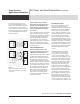
Power Products AC Power and Load Connections (Continued)
Applications Information
More detailed specifications at
www.agilent.com/find/power
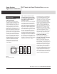
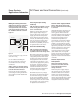
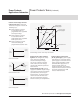
If remote sensing is to be used,
locate the DC distribution termi-
nals as near as possible to the load
terminals. Later in the procedure,
sensing leads will be connected from
the power supply sensing terminals
to the DC distribution terminals as
shown in Figure 2.
Figure 2
Location of DC distribution terminals with
remote sensing (distribution terminals are
shown solid)
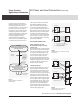
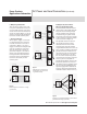
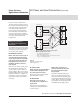
STEP 3. Connect one pair of wires
directly from the power supply output
terminals to the DC distribution ter-
minals, and connect a separate pair of
wires from the distribution terminals
to each load.
There should be no direct connection
from one load to another except by
way of the DC distribution terminals.
(Although for clarity the diagrams
show the load and sensing leads
as straight lines, some immunity
against pick-up from stray magnetic
fields can be obtained by twisting
each pair of load leads and shielding
all sensing leads.)
Decouple Multiple Loads
STEP 4. If required, connect a local
decoupling capacitor across each pair
of distribution and load terminals.
Load decoupling capacitors are often
needed when multiple loads draw
pulse currents with short rise times.
To reduce high frequency mutual
coupling effects under these circum-
stances, capacitors must be connected
directly across the load and distribu-
tion terminals. The capacitors used
for decoupling must be selected to
have a high frequency impedance
that is lower than the impedance
of the wires connected to the same
load, and their connecting leads
must be kept as short as possible to
minimize impedance.
Grounding the System
Since no two ground points have
exactly the same potential, the
idealized concept of a single ground
potential is a snare and a delusion.
In many cases the potential differ-
ence is small, but a difference in two
ground potentials of even a fraction
of a volt could cause amperes of
current to flow through a complete
ground loop. (Ground loop is a ter m
used to describe any conducting path
formed by two separate connections
to ground). Ground loops can cause
serious interference problems when
voltages developed by these currents
are coupled into sensitive signal
circuits.
To avoid ground loop problems,
there must be only one ground
return point in a power supply
system. (A power supply system
includes the power supply, all of its
loads, and all other power supplies
connected to the same loads). The
selection of the best ground return
point depends on the nature and
complexity of the DC wiring. In
large systems, practical problems
frequently tend to force compromises
with the ideal grounding concept.
For example, a rack mounted system
consisting of separately mounted
power supplies and loads generally
has multiple ground connections.
Each instrument usually has its own
chassis tied to the third grounding
wire of its power cord, and the rack
is often connected by a separate wire
Power Supply
+S
+DT
-DT
Load
No. 1
Keep these four load
wires as short as possible,
use large wire size
Load
No. 2
-S
+
-
Power Supply
+S
Load
-S
+
-
With One Load
With Multiple Loads