
Product specifications


133
Power Products AC Power and Load Connections (Continued)
Applications Information
More detailed specifications at
www.agilent.com/find/power
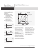
Making the Sensing Connections
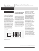
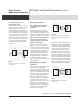
STEP 8. Remove the jumper connections
between the power supply sensing
and output terminals, and connect the
power supply sensing terminals to the
DC distribution terminals as shown in
Figure 12.
Figure 12
Properly grounded power supply system with
remote error sensing
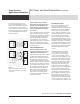
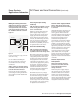
Use an insulated shielded pair
for t he sensing leads. Do not use
the shield as one of the sensing
conductors.
STEP 9. Connect one end of the sensing
lead shield to the DC common point and
leave the other end unconnected.
In nearly all cases t his method of
connecting the sensing shield mini-
mizes ripple at the DC distribution
terminals.
Protect Against Open Sensing
Leads Step
STEP 10. Avoid the possibility of an open
remote sensing path, either on a long-
term or a transient basis.
Opening a sensing lead causes the
power supply output voltage to
increase. Protective circuits in the
supply provide some load protec-
tion by limiting the amount of th e
increase, but eliminating all switch,
relay, or connector contacts from
the remote sensing path helps to
minimize the possibility of any loss
of regulation due to this cause.
Check the Load Wire Rating
STEP 11. Verify that the voltage drop
in the load leads does not exceed the
capabilities of the remote sensing circuit.
Most well regulated power supplies
have an upper limit to the load lead
voltage drop around which remote
sensing can be connected without
losing regulation. This maximum
voltage drop is typically 0.5, 1, or 2
volts, and may apply to the positive,
the negative, or both the positive
and negative output leads. See the
instruction manual for the exact
load lead voltage drop limitations
of a particular power supply.
Remember too, that any voltage
drop lost in the load leads reduces
the maximum voltage available
for use at the load. Either of these
limitations sometimes dictates the
use of a larger wire size than would
be required by wire current rating
or impedance considerations.
Check for Power Supply Oscillation
STEP 12. Verify that the power supply
does not oscillate when remote sensing
is connected.
Although DC and low frequency per-
formance are improved by remote
sensing, phase shifts associated
with long load and sensing leads can
affect the stability of the feedback
loop seriously enough to cause
oscillation. This problem can
frequently be corrected by readjust-
ing a “transient recovery” or “loop
stability” control inside the supply
if the circuit includes one; follow the
adjustment procedure in the manual.
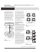
Another remedy that is often effec-
tive is to disconnect the output
capacitor inside the power supply
(some models have a rear panel
jumper that can be removed for this
purpose) and to connect a similar
capacitor across the DC distribution
terminals.
Check for Proper Current
Limit Operation
STEP 13. Check that the operating
point of the current limit circuit has
not been affected by the remote
sensing connections.
With some power supply designs,
the resistance of one of the output
conductors adds to the resistance
used for current limit monitoring
when remote sensing is used. This
reduces the threshold value at which
current limiting begins and makes
readjustment of the current limit
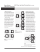
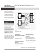
Power Supply
+S
+DT
Load
No. 1
DT and CP
GP
Load
No. 2
-S
+
-