
User's Manual

17
f. Record the output voltage at the digital voltmeter.
g. Adjust autotransformer to the maximum for your line voltage.
h. When the reading settles record the output voltage again. Check that the two recorded readings differ no more than:
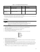
± 0.0030Vdc (6023A)
± 0.0080Vdc (6028A)
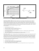
PARD (Ripple And Noise). Periodic and random deviations (PARD) in the unit's output-ripple and noise-combine to
produce a residual ac voltage superimposed on the dc output voltage. Constant-voltage PARD is specified as the
root-mean-square (rms) or peak-to-peak (pp) output voltage in a frequency range of 20Hz to 20MHz.
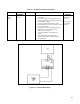
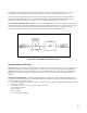
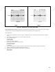
RMS Measurement Procedure. Figure 2-4 shows the interconnections of equipment to measure PARD in Vrms. To
ensure that there is no voltage difference between the voltmeter's case and the unit's case, connect both to the same ac
power outlet or check that the two ac power outlets used have the same earth-ground connection.
Use the common-mode choke as shown to reduce ground-loop currents from interfering with measurement. Reduce noise
pickup on the test leads by using 50Ω coaxial cable, and wind it five turns through the magnetic core to form the
common-mode choke. Proceed as follows:
a. Connect the test equipment as shown in Figure 2-4. Operate the load in constant resistance mode (Amps/Volt) and set
resistance to maximum.
b. Turn the unit's power on, and turn up current setting to full output.
c. Turn up output voltage to:
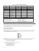
7Vdc (6023A)
20Vdc (6028A)
d. Reduce the resistance of the load to draw an output current of:
29Adc (6023A)
10Adc (6028A)
Check that the unit's CV LED remains lighted.
e. Check that the rms noise voltage at the true rms voltmeter is no more than:
3.0mV rms (6023A)
3.0mV rms (6028A)
Figure 2-4. RMS Measurement Test Setup, CV PARD Test
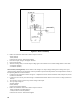
Peak Measurement Procedure. Figure 2-5 shows the interconnections of equipment to measure PARD in Vpp. The
equipment grounding and power connection instructions of PARD rms test apply to this setup also. Connect the
oscilloscope to the + OUT and - OUT terminals through 0.01µF blocking capacitors to protect the oscilloscope's input from