
User's Manual

39
If the failure symptoms include output current oscillation, check if the differentiator circuit is at fault by removing resistor
A2R16 (3.3M ohm ). If oscillations stop, the differentiator is probably at fault.
Troubleshooting Down Programmer
The down programmer decreases the output when either MASTER ENABLE is low or CV ERROR is more negative than
about - 6Vdc. Comparator A4U3B triggers down programming when the voltage at A4U3B-5 is less than about 3Vdc. The
collector-emitter current through transistor A4Q6 increases as the output voltage decreases because of feedback from
voltage divider A4R24-A4R27 at A4U3A-2
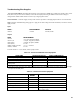
Circuit Included. Down programmer and 8.9V bias supply on A4 power mesh board.
Setup. The Main Troubleshooting Setup, Paragraph 5-73, except connect the external supply to the unit's + OUT ( + ) and -
OUT ( - ) terminals. Apply the ac mains voltage to the bias transformer. Set the external supply (EXTERNAL) and adjust
unit’s voltage setting (INTERNAL) as instructed below.
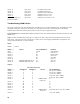
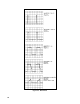
Outputs:
SET VOLTAGE (Vdc)
NODE ( + ) EXT INT SETUP MEASUREMENT
A4U4(OUT) - - 8.9Vdc
A4U3B-7 0 2 unplug TS1 0Vdc
A4U3B-7 10 0 reconnect TS1 0Vdc
A4U3B-7 0 2 0Vdc
A4U3A-2 0 2 unplug TS1 0.43Vdc
A4F1 0 2 0.2Vdc
A4Q6(base) 0 2 1.0Vdc
A4U3A-1 20 2 4.0Vdc
A4F1 20 2 0.11Vdc
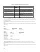
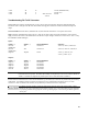
Troubleshooting OVP Circuit
Comparator A2U14D sets and gate A2U17A resets, flipflop A2U14B-A2U14C. TTL low at A2U14-1,8,13 inhibits the
PWM.
Circuit included. OVP Circuit and 2.5V bias supply on A2 control board.
Setup. The Main Troubleshooting Setup, page 29, except connect the external supply to the unit's + OUT ( + ) and - OUT
( - ) terminals. Apply the ac mains voltage to the bias transformer. Adjust the unit's OVP limit to 15Vdc. Set the external
supply (EXTERNAL) as instructed below.