
Service manual

13
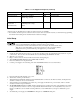
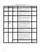
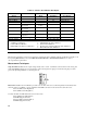
Table 2-2. Calibration Procedure (continued)
TEST TESTED
VARIABLE
TEST POINTS TEST SEQUENCE AND ADJUSTMENTS EXPECTED
RESULTS
Power
Limit
Adjust.
V(OUT)
I(OUT)
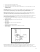
a. Perform I-MON F/S Adjust before
proceeding.
b. Connect the unit to the ac power line via the
external variable auto-transformer which is set
to nominal line voltage.
c. Connect a 0.25Ω, 250W (6023A), 2.3Ω,
250W (6028A) resistor across the unit's output
and turn on ac power.
d. Set voltage control to 9V (6023A) 9V≥ 3V
(6028A) and current control to 30.2A
(6023A), 10.2A (6028A)
e. Set auto-transformer to minimum line
voltage.
f. Turn A2R25 fully counterclockwise.
g. Slowly adjust A2R25 clockwise until CC
LED just lights.
30.2A 7.55V for
CC operation
(6023A)
10.2A, 23V for
CC operation
(6028A)
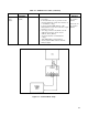
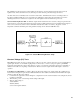
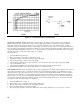
Figure 2-1. Common Mode Setup