
Service manual


30
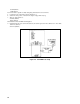
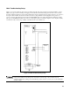
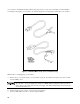
As a convenience in implementing the troubleshooting setup, prepare cord sets as shown in Figure 3-2. This facilitates
connecting the unit's input power receptacle to the external supply and connecting the bias transformer to the ac mains.
Figure 3-2. Modified Mains Cord Set For Troubleshooting
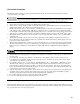
With the mains cord unplugged proceed as follows:
a.
Remove the top cover and the inside cover as described on page 26. Set switch S4 (front-left corner of the A1 main
board) in TEST position.
If switch is not in the TEST position and remains in the NORM position, completion of step e below will
allow the unit to develop its 320Vdc bus voltage across PFETs A3Q3 and A3Q4 and will connect the ac
mains voltage to the output of the external power supply. This will probably damage the external supply
and is a shock hazard to you.
b. Install control board test connector onto the A2J3 card edge fingers.
c.
Connect a 50Ω, 10W, load resistor to the unit's output terminals.