
Service manual


92
Figure A-8. Remote Control
Power-On Preset
This open collector output line J3-6, provides a logic low pulse ( Preset-On -Power ) to the user that can be used to
initialize or delay a system's operation until + 5V Reg. supply has stabilized. The pulse is generated after primary power is
turned on and also after resumption of power following momentary ac dropout or conditions in which line voltage drops
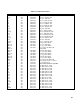
below approximately 70% of the nominal. See Table Al for
Preset-On-Power signal specifications.
The
Preset-On-Power circuit also ensures that terminal J3-17 ( EOVERVOLTAG ) will be high when the supply is
turned on. This protects against unwanted Multiple Supply System Shutdowns when using J3-17 (
EOVERVOLTAG ) to
remote trip additional power supplies.
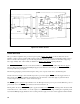
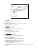
The following paragraphs provide a brief description of the power-on preset circuit, refer to schematic diagram:
Circuits on the Power Supply's A2 Control Board produce a power-clear signal, ( PCLR ), when the supply is turned on.
These circuits hold
PCLR low until the unregulated input to the A2 Board's + 5Vdc bias supply is greater than about
11Vdc, an input voltage sufficient to assure + 5Vdc bias output.
This
PCLR signal is coupled through terminal J1-15 to the 002 Option board's power-on preset circuit. When the power-on
preset circuit receives the
PCLR signal, transistors U14A and U14C turn off.
Turning U14A off causes a
DROPOUT signal to appear at terminal J3-19 ( DROPOUT ). Turning U14C off causes U14B
and U14D to turn on. When U14B is on, it holds output J3-17 (
EOVERVOLTAG ) high. Holding J3-17 high will prevent
any unwanted Multiple Supply Shutdowns from occurring when the supply is wired for such an application. When U10D is