INSTALLATION GUIDE Agilent Technologies MPS Mainframe Model 66000A Agilent Part No. 66000-90001 Microfiche Part No.
CERTIFICATION Agilent Technologies certifies that this product met its published specifications at time of shipment from the factory. Agilent Technologies further certifies that its calibration measurements are traceable to the United States National Bureau of Standards, to the extent allowed by the Bureau’s calibration facility, and to the calibration facilities of other International Standards Organization members.
SAFETY SUMMARY The following general safety precautions must be observed during all phases of operation, service, and repair of this mainframe. Failure to comply with these precautions or with specific warnings elsewhere in this guide violates safety standards of design, manufacture, and intended use of the mainframe. Agilent Technologies assumes no liability for the customer's failure to comply with these requirements.
SAFETY SYMBOL DEFINITIONS Symbol Description Symbol Description Direct current Terminal for Line conductor on permanently installed equipment Alternating current Caution, risk of electric shock Both direct and alternating current Caution, hot surface Three-phase alternating current Caution (refer to accompanying documents) Earth (ground) terminal In position of a bi-stable push control Protective earth (ground) terminal Out position of a bi-stable push control Frame or chassis terminal On (
DECLARATION OF CONFORMITY According to ISO/IEC Guide 22 and CEN/CENELEC EN 45014 Manufacturer’s Name and Address Responsible Party Agilent Technologies, Inc. 550 Clark Drive, Suite 101 Budd Lake, New Jersey 07828 USA Alternate Manufacturing Site Agilent Technologies (Malaysia) Sdn.
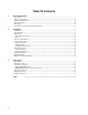
Table Of Contents 1. General Information Introduction ..................................................................................................................................................9 Safety Considerations...................................................................................................................................9 Instrument Identification ..............................................................................................................................
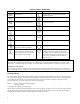
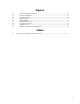
Figures 2-1. 2-2. 2-3. 2-4. 2-5. 3-1. 3-2. 3-3. 3-4. Power Cord Plug Configurations............................................................................................14 Power Cord Installation ..........................................................................................................15 Rear Panel Switches ...............................................................................................................16 Switch Settings ..................................................
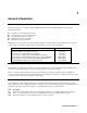
1 General Information Introduction This guide describes how to install the Agilent 66000A Modular Power System (MPS) Mainframe.
Options and Parts The following options are available with the mainframe: Option 908 909 0L2 831 833 834 841 843 845 846 847 848 Description Rack Mounting Kit Rack Mounting Kit with handles Extra Manual Set Power Cords 12 AWG unterminated power cord 1.5 mm2 unterminated power cord 10 AWG unterminated power cord 20 A/250 V NEMA 6-20P plug with 12 AWG power cord 20 A/250 V JIS C8303 plug with 12 AWG power cord 16 A/220 V IEC 309 plug with 1.
Specifications and Supplemental Characteristics Table 1-1 lists the specifications and supplemental characteristics of the MPS mainframe. Module specifications are included in the appropriate module User’s Guide. Specifications are warranted in the temperature range of 0 to 55 degrees C. Supplemental characteristics are not warranted, but are descriptions of minimum, maximum, or average performance that has been determined by design or type testing. Table 1-1.
Table 1-1. Specifications and Supplemental Characteristics (continued) INH/FLT Characteristics Maximum Ratings: ± 16.5 V between pins 3 and 4 + 16.5 V between pins 1 and 2 - 5.3 V between pins 1 and 2 INH (10k pull-up): IIL @ 4 V = 700 µA IIH @ 5.25 V = 200 µA VIL = 0.8 V maximum VIH = 2.0 V minimum DFI (open collector): VCE = 0.4 V maximum @ IC = 2.2 mA IIH @ 5.25 V = 200 µA VIL = 0.8 V maximum VIH = 2.0 V minimum Dimensions Width: Height: Depth: 426 mm (16.75 in) 178 mm (7 in), add 13 mm (0.
2 Installation Installation When you receive your mainframe, first look for any obvious damage that could have occurred during shipment. If there is damage, notify the carrier and the nearest Agilent Sales Office immediately. Warranty information is printed behind the cover page of this manual. Save the shipping carton and packing materials in case the mainframe has to be returned to Agilent Technologies in the future.
Fuses The mainframe fuse is located inside the mainframe. Refer to the mainframe Service Manual for information about replacing the fuse. Power Cord Installation The power cord supplied with your mainframe may or may not include a power plug. Figure 2-1 shows the various power plugs. Ring terminals are attached to one end of the power cord to facilitate mainframe installation. Figure 2-1.
Figure 2-2. Power Cord Installation Location and Cooling Bench Operation Chapter 1 gives the dimensions of your mainframe. The mainframe has plastic feet that are shaped to ensure self-alignment when stacked with other Agilent System II cabinets. The feet may be removed for rack mounting. Your mainframe must be installed in a location that allows sufficient space at the sides and rear of the mainframe for adequate air circulation. Do not block the vents at the sides and rear of the mainframe.
Rear Panel Switches The six-position rear panel switch is shown in the following figure. Figure 2-3. Rear Panel Switches Address Switches Address switches A0 through A4 set the primary GPIB address. The address is set in binary, A0 being the least significant bit and A4 being the most significant bit. Figure 2-3 shows the factory-set address of "5" (binary 00101). Any address from decimal 0 to decimal 30 is a valid GPIB address. Refer to the following diagram for switch settings.
Slot Location Secondary Address Note Mainframe Slot Locations/Addresses Mainframe Mode Switch = MAIN 0 1 2 3 4 5 6 7 0 0 1 2 3 4 5 6 7 8 1 9 Mainframe Mode Switch = AUX 2 3 4 5 6 10 11 12 13 14 7 15 Secondary addresses are reserved for the mainframe whether modules occupy the associated slot locations or not. You may want to apply stick-on labels over the slot locations of the mainframe to indicate that the modules installed in the auxiliary mainframe are at secondary addresses 8 to 15.
Module Installation Note A fully loaded mainframe can weigh over 36 kg (80 lbs). Install the mainframe into the rack before installing the modules into the mainframe. All modules install through the front of the mainframe. Installation (and removal) can be accomplished even when the mainframe is rack-mounted. To install the modules in the mainframe, refer to Figure 2-5 and proceed as follows: ■ ■ ■ ■ Use a flat-bladed screwdriver and release the pull tab by pressing down.
■ There must be no or minimal current flowing through the connector pins at the back of the module that is being removed. This can be accomplished by disabling the module. If this precaution is repeatedly violated at high current, the connector pins at the back of the module will be damaged. ■ There must be no activity on the GPIB bus, the trigger connectors, or the FLT/INH connector of the mainframe when a module is removed.
3 Connections Rear Panel Figure 3-1 shows where all of the rear panel connections to the mainframe are made. Figure 3-1. Rear Panel Connections Module Connections Wire connections to the modules are made using a separate module connector that is supplied with each module. After the module connector has been wired, it simply attaches to the back of the mainframe. You can attach the module connector to the mainframe either before or after the module is installed.
Controller Connections If you have only one MPS mainframe in your system, simply connect it to the controller using the GPIB cable. If you have more than one mainframe, or if you also have an Agilent 667xA, 665xA, 664xA, or 603xA power supply in your system, you can use the serial-link cable supplied with your mainframe to facilitate connections. Figure 3-2 illustrates the serial-link connections. Multiple MPS Mainframes See Figure 3-2.
Figure 3-2.
Figure 3-3. Digital Connector FLT Output (pins 1 and 2) Used to indicate that a fault has occurred on one of the modules in the mainframe. Pins 1 and 2 are the open-collector output of an optocoupler, with pin 1 the collector and pin 2 the emitter. When a fault has occurred, pin 1 is driven low with respect to pin 2 (negative-true). INH Input (pin 3) Used to shut down the outputs of all modules in the mainframe that have been enabled to respond to the remote inhibit function.
Figure 3-4.
Index A addresses, 16 address switch, 16 Agilent 603xA, 10, 11, 16, 22 Agilent 664xA, 10, 11, 16, 22 Agilent 665xA, 10, 11, 16, 22 Agilent 667xA, 10, 11, 16, 22 AUX, 16, 17, 22 B BNC connectors, 24 C characteristics, 11 connector, 18, 19, 21 connector - installation, 21 D digital connector plug, 10, 22, 24 documentation, 9 F feet, 15 filler panel, 10, 13, 18 FLT/INH, 12, 24 frame mode, 17, 22 frame switch, 16, 22 fuses, 14 H GPIB address, 16, 22 GPIB interface, 11 K keyboard, 22 L line current, 11 line volt
Agilent Sales and Support Offices For more information about Agilent Technologies test and measurement products, applications, services, and for a current sales office listing, visit our web site: http://www.agilent.com/find/tmdir You can also contact one of the following centers and ask for a test and measurement sales representative. United States: Agilent Technologies Test and Measurement Call Center P.O.
Manual Updates The following updates have been made to this manual since the print revision indicated on the title page. 4/15/00 All references to HP have been changed to Agilent. All references to HP-IB have been changed to GPIB. 6/21/02 The serial number and option number information in chapter 1 has been updated.