
User`s guide
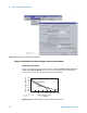
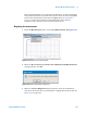
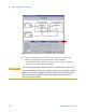
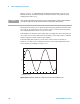

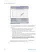

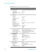
Table Of Contents
- Title Page
- Contents
- Getting Started
- Introduction and Measurement
- Phase Noise Basics
- Expanding Your Measurement Experience
- Starting the Measurement Software
- Using the Asset Manager
- Using the Server Hardware Connections to Specify the Source
- Setting GPIB Addresses
- Testing the 8663A Internal/External 10 MHz
- Testing the 8644B Internal/External 10 MHz
- Viewing Markers
- Omitting Spurs
- Displaying the Parameter Summary
- Exporting Measurement Results
- Absolute Measurement Fundamentals
- Absolute Measurement Examples
- Residual Measurement Fundamentals
- What is Residual Noise?
- Assumptions about Residual Phase Noise Measurements
- Calibrating the Measurement
- Measurement Difficulties
- Residual Measurement Examples
- FM Discriminator Fundamentals
- FM Discriminator Measurement Examples
- AM Noise Measurement Fundamentals
- AM Noise Measurement Examples
- Baseband Noise Measurement Examples
- Evaluating Your Measurement Results
- Advanced Software Features
- Reference Graphs and Tables
- Approximate System Noise Floor vs. R Port Signal Level
- Phase Noise Floor and Region of Validity
- Phase Noise Level of Various Agilent Sources
- Increase in Measured Noise as Ref Source Approaches DUT Noise
- Approximate Sensitivity of Delay Line Discriminator
- AM Calibration
- Voltage Controlled Source Tuning Requirements
- Tune Range of VCO for Center Voltage
- Peak Tuning Range Required by Noise Level
- Phase Lock Loop Bandwidth vs. Peak Tuning Range
- Noise Floor Limits Due to Peak Tuning Range
- Tuning Characteristics of Various VCO Source Options
- 8643A Frequency Limits
- 8644B Frequency Limits
- 8664A Frequency Limits
- 8665A Frequency Limits
- 8665B Frequency Limits
- System Specifications
- System Interconnections
- PC Components Installation
- Overview
- Step 1: Uninstall the current version of Agilent Technologies IO libraries
- Step 2: Uninstall all National Instruments products.
- Step 3: Install the National Instruments VXI software.
- Step 4: Install the National Instruments VISA runtime.
- Step 5: Install software for the NI Data Acquisition Software.
- Step 6: Hardware Installation
- Step 7. Finalize National Instruments Software Installation.
- Step 8: System Interconnections
- Step 9: Install Microsoft Visual C++ 2008 Redistributable Package use default settings
- Step 10: Install the Agilent I/O Libraries
- Step 11: Install the E5500 Phase Noise Measurement software.
- Step 12: Asset Configuration
- Step 13: License Key for the Phase Noise Test Set
- Overview
- PC Digitizer Performance Verification
- Preventive Maintenance
- Service, Support, and Safety Information
- Safety and Regulatory Information
- Safety summary
- Equipment Installation
- Environmental conditions
- Before applying power
- Ground the instrument or system
- Fuses and Circuit Breakers
- Maintenance
- Safety symbols and instrument markings
- Regulatory Compliance
- Declaration of Conformity
- Compliance with German noise requirements
- Compliance with Canadian EMC requirements
- Service and Support
- Return Procedure
- Safety and Regulatory Information

200 Agilent E5505A User’s Guide
6
Absolute Measurement Examples
Table 28 Parameter data for the microwave source measurement
Step Parameters Data
1 Type and Range Tab
Measurement Type
•
Start Frequency
•
Stop Frequency
•
Minimum Number of Averages
FFT Quality
•
Absolute Phase Noise (using a phase locked loop)
•
10 Hz
•
4 E + 6 Hz
•
4
•
Fast
2Sources Tab
Carrier Source
•
Frequency
•
Power
•
Carrier Source Output is
connected to:
Detector Input
•
Frequency
Reference Source
•
Frequency
•
Reference Source Power
VCO Tuning Parameters
•
Nominal Tune Constant
•
Tune Range ± Center Voltage
•
Input Resistance
•
12 E + 9 Hz
•
10 dBm
•
Test Set
•
600 E +6 Hz
•
600 E +6 Hz (same as Carrier Source Frequency)
•
16 dBm
•
•
40 E +3 Hz/V
•
± 10 Volts
•
0 Volts
•
600 Ω
3Cal Tab
•
Phase Detector Constant
•
VCO Tune Constant
•
Phase Lock Loop Suppression
•
If Limit is exceeded
•
Measure Phase Detector Constant
•
Calculate from expected VCO Tune Constant
•
Verify calculated phase locked loop suppression
•
Show Suppression Graph
4 Block Diagram Tab
•
Carrier Source
•
Downconverter
•
Reference Source
•
Timebase
•
Phase Detector
•
Test Set Tune Voltage
Destination
•
VCO Tune Mode
•
Manual
•
Agilent N5502A/70422A
•
Agilent 8644B (System Control)
•
None
•
Automatic Detector Selection
•
Reference Source
•
DCFM
5Test Set Tab
Input Attenuation
LNA Low Pass Filter
•
LNA Gain
•
DC Block
•
PLL Integrator Attenuation
•
0 dB
•
20 MHz (Auto checked)
•
Auto Gain (Minimum Auto Gain –14 dB)
•
Not checked
•
0 dBm