
Specifications

5-14
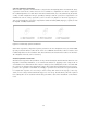
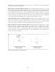
5.3 Transformer measurement
A transformer is one end-product of an inductor so, the measurement techniques are the same as
those used for inductor measurement. Figure 5-18 shows a schematic with the key measurement
parameters of a transformer. This section describes how to measure these parameters, including L,
C, R, and M.
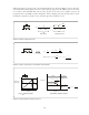
Figure 5-18. Transformer parameters
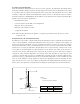
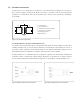
5.3.1 Primary inductance (L1) and secondary inductance (L2)
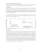
L1 and L2 can be measured directly by connecting the instrument as shown in Figure 5-19. All other
windings should be left open. Note that the inductance measurement result includes the effects of
capacitance. If the equivalent circuit analysis function of the Agilent’s impedance analyzer is used,
the individual values for inductance, resistance, and capacitance can be obtained.
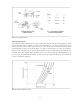
Leakage inductance is a self-inductance due to imperfect coupling of the transformer windings and
resultant creation of leakage flux. Obtain leakage inductance by shorting the secondary with the
lowest possible impedance and measuring the inductance of the primary as shown in Figure 5-20.
Figure 5-19. Primary inductance measurement Figure 5-20. Leakage inductance measurement
C
M
L
1
C
1
R
1
R
2
C
2
L
2
L : Primary inductance
1
L : Secondary inductance
2
C
1
, C : Distributed capacitance of windings
2
R
1
, R : DC resistance of windings
2
C: Inter-winding capacitance
M: Mutual inductance