
Specifications


5-21
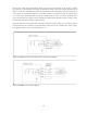
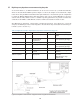
Figure 5-30. C-V measurement setup using 4TP cable extension
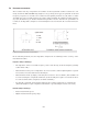
Figure 5-31. C-V measurement setup using 2TP cable extension
Impedance analyzer/LCR meter
Agilent test cables
Wafer prober
Chuck
b
Interconnecting the outer shielding
conductors of two BNC connectors at
“a” is absolutely required to properly
terminate the 4TP.
Interconnecting the outer shielding
conductors of probes at “b” is
recommended to make the 2TP
configuration.
a
Hc
Hp
Lp
Lc
Impedance analyzer/LCR meter
Agilent test cables
Wafer prober
Chuck
In order to extend the 4TP configuration up
to the position of probe heads, don’t
electrically interconnect the outer
shielding conductors of the cables here.
Interconnecting the outer shielding
conductors of four cables at “a” is
absolutely required to properly
terminate the 4TP.
Interconnecting the outer shielding
conductors of probes at “b” is
recommended to make the 2TP
configuration.
b
a
Hc
HpLp
Lc