
Specifications


5-29
5.10 Balanced device measurement
When a balanced DUT (such as balanced cable or the balanced input impedance of a differential
amplifier) is measured, it is necessary to connect a “balun” (balance-unbalance) transformer
between the instrument and the DUT. Looking from the DUT side, the UNKNOWN terminals of the
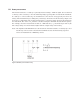
impedance measurement instrument are in an “unbalanced” configuration. Figure 5-40 (a) shows an
example of an auto-balancing bridge instrument. Its Low terminal is considered a virtual ground
because it is held at approximately a 0 V potential. When a 1:1 balun transformer is connected as
shown in Figure 5-40 (b), the instrument can measure a balanced DUT directly.
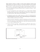
Figure 5-40. Balanced device measurement
An actual balun transformer has a limited frequency range. The measurement must be made within
its frequency range. In addition to Agilent’s balanced/unbalanced converters, various types of com-
mercial balun transformers are available for various frequency ranges. To select the appropriate
balun transformer, check the frequency range and the impedance of the transformer’s balanced
(DUT) side. Its impedance should be close to the characteristic impedance of the DUT. The imped-
ance of the unbalanced side should be 50 or 75 Ω as appropriate for the measurement instrument.
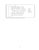
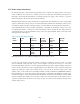
Open/short/load compensation for the balun transformer is required when the turns ratio of the
balun transformer used is not 1:1, or when an accurate measurement is needed. Open/short com-
pensation is not adequate because the balun transformer will produce both magnitude (|Z|) and
phase errors due to its transfer function characteristic. The terminal connectors of the balanced side
should be connectable for both the standard devices used for open/short/load compensation and the
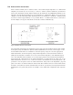
DUT. Figures 5-41 (a) through (d) show an example of an actual balun configuration and compensa-
tion.