
Specifications


Measurement accuracy can be improved by taking advantage of the equivalent circuit analysis.
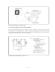
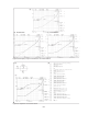
Figure 5-52 (a) shows an Ls-Q measurement example for an inductor. In this example, an impedance
analyzer measures the Q value at 10 MHz. Measured data read by MARKER is Ls = 4.78 µH and
Q = 49.6. The Q measurement accuracy for this impedance at 10 MHz is calculated from the instru-
ment’s specified D measurement accuracy of ±0.011, and the true Q value will be between 32 and
109. The reason that the uncertainty of the Q value is so high is that the small resistive component
relative to reactance cannot be measured accurately. It is possible to measure the resistive
component accurately if the inductive component is canceled by the capacitance connected in series
with the inductor. When a loss-less capacitor of 1/(ω
2
L) = 53 pF is connected, the inductor will
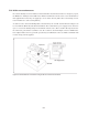
resonate at 10 MHz. (In this example, a 46 pF capacitor is used for resonance.) Figure 5-52 (b) shows
the |Z| - θ measurement results when a 46 pF capacitor is connected. This result can be modeled
using circuit mode D, and the value of R is calculated to be 8.51 Ω. The value of L is obtained as
4.93 µH. Since the equivalent circuit analysis function uses approximately 8.51 × √
—
2 Ω data to calcu-
late the R value, the specified measurement accuracy for a 12 Ω resistance measurement can be
used and is ±1.3 percent. Therefore, the Q value can be calculated from Q = ωLs/R = 36.4 with an
accuracy of ±2.4% (sum of the L accuracy and R accuracy.) In this measurement, the capacitance
value does not have to be exactly the calculated value but the loss of the capacitor should be very
small because it will affect the calculated Q value.
Figure 5-52. Q measurement accuracy improvement
5-41
(a)
(b)