
Specifications


2-4
2.2 Operating theory of practical instruments
The operating theory and key functions of the auto balancing bridge instrument are discussed
in Sections 2.3 through 2.4. A discussion on the RF I-V instrument is described in Sections 2.5
through 2.7.
2.3 Theory of auto-balancing bridge method
The auto-balancing bridge method is commonly used in modern LF impedance measurement instru-
ments. Its operational frequency range has been extended up to 110 MHz.
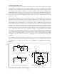
Basically, in order to measure the complex impedance of the DUT it is necessary to measure the
voltage of the test signal applied to the DUT and the current that flows through it. Accordingly, the
complex impedance of the DUT can be measured with a measurement circuit consisting of a signal
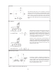
source, a voltmeter, and an ammeter as shown in Figure 2-2 (a). The voltmeter and ammeter mea-
sure the vectors (magnitude and phase angle) of the signal voltage and current, respectively.
Figure 2-2. Principle of auto-balancing bridge method
DUT
I
V A
High Low
Z =
I
V
(a) The simplest model for
impedance measurement
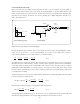
DUT
V
x
V
r
High Low
I
x
I
r
= R
r
Z
x
=
I
x
V
x
V
r
V
x
R
r
(b) Impedance measurement
using an operational amplifier