
Specifications

2-14
The induced errors are dependent upon test frequency, test fixture, test leads, DUT connection
configuration, and surrounding conditions of the DUT. Hence, the procedure to perform compensa-
tion with actual measurement setup is the key to obtaining accurate measurement results. The
compensation theory and practice are discussed comprehensively in Section 4.
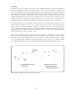
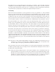
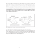
2.4.7 Guarding
When in-circuit measurements are being performed or when one parameter of a three-terminal
device is to be measured for the targeted component, as shown in Figure 2-12 (a), the effects of par-
alleled impedance can be reduced by using guarding techniques. The guarding techniques can also
be utilized to reduce the outcome of stray capacitance when the measurements are affected by the
strays present between the measurement terminals, or between the DUT terminals and a closely
located conductor. (Refer to Section 3.5 for the methods of eliminating the stray capacitance effects.)
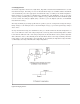
The guard terminal is the circuit common of the auto-balancing bridge and is connected to the
shields of the four-terminal pair connectors. The guard terminal is electrically different from the
ground terminal, which is connected directly to the chassis (Figure 2-12 (b).) When the guard is
properly connected, as shown in Figure 2-12 (c), it reduces the test signal's current but does not
affect the measurement of the DUT’s impedance (Zx) because Zx is calculated using DUT current (Ix.)
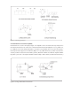
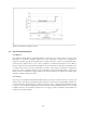
The details of the guard effects are described as follows. The current (I
1
) which flows through Z
1
,
does not flow into the ammeter. As long as I
1
does not cause a significant voltage drop of the applied
test signal, it scarcely influences on measurements. The current I
2
, which is supposed to flow
through Z
2
, is small and negligible compared to Ix, because the internal resistance of the ammeter
(equivalent input impedance of the auto-balancing bridge circuit) is very low in comparison to Z
2
. In
addition, the potential at the Low terminal of the bridge circuit, in the balanced condition, is zero
(virtual ground.) However, if Z
2
is too low, the measurement will become unstable because ammeter
noise increases.
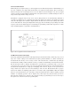
Note: In order to avoid possible bridge unbalance and not cause significant measurement errors, Z
2
should not be lower than certain impedance. Minimum allowable value of Z
2
depends on Zx,
test cable length, test frequency, and other measurement conditions.
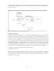
The actual guard connection is shown in Figure 2-12 (d). The guard lead impedance (Zg) should be
as small as possible. If Zg is not low enough, an error current will flow through the series circuit of
Z
1
and Z
2
and, it is parallel with Ix.
Note: Using the ground terminal in place of the guard terminal is not recommend because the
ground potential is not the true zero reference potential of the auto-balancing bridge circuit.
Basically, the ground terminal is used to interconnect the ground (chassis) of the instrument
and that of a system component, such as an external bias source or scanner, in order to
prevent noise interference that may be caused by mutual ground potential difference.