
Specifications


3.1.1 Two-terminal configuration
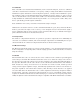
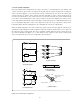
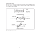
The two-terminal (2T) configuration is the simplest method of connecting a DUT but contains many
error sources. Lead inductances (L
L
), lead resistances (R
L
), and stray capacitance (Co) between two
leads are added to the measurement result (see Figure 3-2.) Contact resistances (R) between the test
fixture’s electrodes and the DUT are also added to measured impedance. Because of the existence of
these error sources, the typical impedance measurement range (without doing compensation) is lim-
ited to 100 Ω to 10 kΩ.
Figure 3-2. Two-terminal (2T) configuration
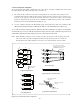
3.1.2 Three-terminal configuration
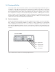
The three-terminal (3T) configuration employs coaxial cables to reduce the effects of stray capaci-
tance. The outer shielding conductors of the coaxial cables are connected to the guard terminal.
Measurement accuracy is improved on the higher impedance measurement range but not on the
lower impedance measurement range, because lead impedances (wL
L
and R
L
) and contact resis-
tances (Rc) still remain (see Figure 3-3.) The typical impedance range will be extended above 10 kΩ.
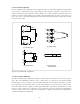
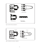
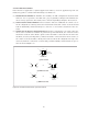
If the two outer conductors are connected to each other at the ends of the cables as shown in Figure
3-4, the accuracy for the lower impedance measurement is improved a little. This configuration is
called the shielded 2T configuration.
3-2
DUT
V
Null
detector
(a) Schematic diagram
H
p
H
c
L
c
L
p
R
s
R
r
(b) Connection image
H
p
H
c
L
c
L
p
(d) Typical impedance
measurement range
(c) Residual parameters
H
p
H
c
L
c
L
p
DUT
R
L
L
L
R
C
R
C
C
O
R
L
L
L
1 m 10 m 100 m 1 10 100 1 K 10 K 100 K 1 M 10 M (Ω)