
Specifications


4.0 Measurement Error and Compensation
4.1 Measurement error
For real-world measurements, we have to assume that the measurement result always contains
some error. Some typical error sources are:
• Instrument inaccuracies (including DC bias inaccuracy, test signal level inaccuracy, and
impedance measurement inaccuracy)
• Residuals in the test fixture and cables
• Noise
The DUT’s parasitics are not included in the above list because they are a part of the DUT. The para-
sitics are the cause of component dependency factors (described in Section 1.5) and dominate the
real characteristics of components. The objective of component measurement is to accurately deter-
mine the real value of a component including parasitics. In order to know the real values of the
DUTs, we need to minimize the measurement errors by using proper measurement techniques. In
the listed error sources, the residuals in the test fixture and test cables can be compensated for if
they are constant and stable.
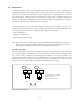
4.2 Calibration
Calibration verifies instrument accuracy by comparing the instrument with "standard devices." To
calibrate an instrument, standard devices are connected at the calibration plane and the instrument
is adjusted (through computation/data storage) so that it measures within its specified accuracy.
The calibration plane indicates the electrical reference plane at which the standard devices are con-
nected and measured. Accordingly, calibration defines the calibration plane at which the specified
measurement accuracy can be obtained.
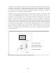
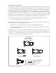
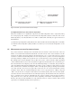
The calibration plane of auto-balancing bridge instruments is at the UNKNOWN BNC connectors
(see Figure 4-1.) When the cable length correction is performed, the calibration reference plane
moves to the tip of the test cables. After an auto-balancing bridge instrument is shipped from the
factory, calibration is usually required for maintenance and service purposes. To maintain the
instrument within the specified accuracy, calibration should be performed periodically at the rec-
ommended calibration intervals (typically once a year.)
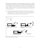
Figure 4-1. Calibration plane of auto-balancing bridge instruments
Precision LCR meter
Calibration plane
Side view
(a) Without cable extension
Calibration plane
Side view
(b) When cable length correction is performed for
Agilent test cables (x = 1, 2, and 4 [m])
x [m]
4-1