
Specifications


4.5 Measurement error induced by cable extension
4.5.1 Error induced by four-terminal pair (4TP) cable extension
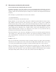
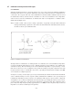
A simplified schematic of test cable extension for the auto-balancing bridge instrument is shown in
Figure 4-11. Extending a 4TP measurement cable from the instrument will cause a magnitude error
and phase shift of the measurement signal according to the extension cable length and measurement
frequency.
The following two problems will arise from the cable extension:
(1) Bridge unbalanced
(2) Error in the impedance measurement result
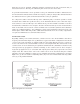
Bridge unbalance is caused by the phase shift in the feedback loop that includes the range resistor,
(Rr), amplifier, and the Lp and Lc cables. If the Lp or Lc cable is too long, it causes a significant
change in phase angle of range resistor current (I
Rr
) flowing through the feedback loop. The vector
current (I
Rr
) cannot balance with the DUT current vector because of the phase error and, as a result
the unbalance current that flows into the Lp terminal is detected by the unbalance detector
(which annunciates the unbalance state to digital control section.) Some instruments such as the
Agilent 4294A impedance analyzer can compensate for the effect of a long extension cable by
producing an intentional phase shift in the feedback loop.
The bridge unbalance is also caused by a standing wave (an effect of reflection) generated when the
cable length is not sufficiently shorter than the test signal wavelength. A guideline for the
cable length limitation caused by this effect is given by the following equation (as described in
Section 3.3.3.)
F [MHz] x L [m] ≤ 15
The errors in impedance measurement results are mainly caused by the phase shift, attenuation,
and reflection of test signal on the cables connected to the Hp and Lc terminals. These errors can be
corrected by the instrument if the propagation constants and the length of the cable are known.
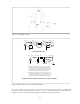
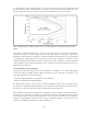
These two problems are critical only at high frequencies (typically above 100 kHz), and Agilent’s
impedance measurement instruments can compensate for Agilent-supplied test cables. In the lower
frequency region, the capacitance of the cable will only degrade the measurement accuracy without
affecting the bridge balance. This effect of the cable extension is shown in Figure 4-12.
4-11