
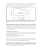
Specifications


4.7.3 Compensation method
As the error source model is different for the coaxial and non-coaxial sections of the test fixture, the
compensation method is also different.
Electrical length compensation eliminates measurement errors induced by the phase shift in the
coaxial section. Agilent RF impedance analyzers and RF LCR meters facilitate the electrical length
compensation by allowing you to choose the model number of the desired test fixture from among
the displayed list, instead of entering the specified electrical length of that test fixture to the instru-
ment. (It is also possible to input the specified electrical length value.)
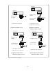
Open/short compensation is effective for residuals in the non-coaxial section. It is based on the
same compensation theory as described for low frequency measurements. (Refer to Section 4.3.2 for
details.) The Yo and Zs can be determined by measuring with the contact terminals opened and
shorted, respectively.
As the test fixture is configured with the coaxial and non-coaxial sections, both compensations are
required to minimize combined errors. Load compensation is not required for normal measure-
ments using Agilent-supplied test fixtures.
When a test port extension or a user-fabricated test fixture is used, error sources will not match the
model assumed for the open/short compensation and they will affect measurement results. In such
cases that measurement errors cannot be removed sufficiently, consider attempting the
open/short/load compensation. Actually, the open/short/load compensation is substituted by the
open/short/load calibration using working-standard devices because these two functions are equiva-
lent to each other. Note that when the open/short/load calibration is executed at measurement ter-
minals, the test port calibration data is invalidated (because the calibration plane is moved.)
Consequently, measurement accuracy depends on the calibrated accuracy of the short and load
working-standard devices (open calibration requires no device) as well as the proper contact when
these standard devices are inserted into the test fixture. It is important that special consideration be
given to the precision of the standard values, contact resistance, and positioning of the standard
device on the test fixture.
4.7.4 Precautions for open and short measurements in RF region
To discuss calibration and compensation issues, we need to consider how residual parameters have
large effects on measurement results at high frequencies.
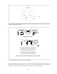
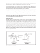
Assume that, for example, a residual inductance of 0.1 nH and a stray capacitance of 0.1 pF exist
around the measurement terminals of the test fixture. Notice how the effects of these small residuals
differ depending on frequency. Relationships of the residual parameter values to the typical imped-
ance measurement range are graphically shown in Figure 4-16. In the low frequency region, the
residual parameter values are much smaller than the values of normally measured devices. It is
because the capacitors and inductors, which are designed for use in low frequency electronic equip-
ment, possess large values compared to small residuals. In the high frequency region, however,
devices such as those employed for higher frequency circuits and equipment have lower values. In
the frequency range typically above 100 MHz, the majority of the DUTs are low value devices (in the
low nanohenries and the low picofarads) and their values come close to the values of the residuals.
4-18