
Specifications

4.7.8 Practical compensation technique
The calibration and compensation methods suitable for measurement are different depending on
how the test cable or fixture is connected to the test port. The following is a typical guideline for
selecting appropriate calibration and compensation methods.
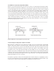
Measurements using an Agilent test fixture without a test port extension
To make measurements using a test fixture connected directly to the test port, first perform calibra-
tion at the test port. After calibration is completed, connect the test fixture to the test port and
then perform electrical length compensation (for the test fixture’s electrical length) and open/short
compensation.
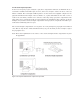
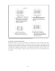
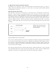
Measurement using a test port extension
When the measurement needs to be performed using a test port extension or a non-Agilent test fix-
ture, it is recommended that the open/short/load calibration be performed at the measurement ter-
minals of the test fixture. Typically, this method is applied when unknown devices are measured
using a component handler. Because coaxial terminations do not match geometrically with the con-
tact terminals of the test fixture or of the component handler, short and load devices whose values
are defined or accurately known are required as substitution standards. (Open calibration requires
no device.) Compensation is not required because measurements are made at the calibration plane.
4.8 Measurement correlation and repeatability
It is possible for different measurement results to be obtained for the same device when the same
instrument and test fixture is used. There are many possible causes for the measurement discrepan-
cies, as well as residuals. Typical factors for measurement discrepancies in RF impedance measure-
ments are listed below.
• Variance in residual parameter value
• A difference in contact condition
• A difference in open/short compensation conditions
• Electromagnetic coupling with a conductor near the DUT
• Variance in environmental temperature
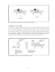
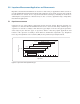
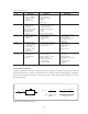
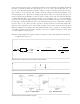
4.8.1 Variance in residual parameter value
Effective residual impedance and stray capacitance vary depending on the position of the DUT
connected to the measurement terminals. Connecting the DUT to the tip of the terminals increases
residual inductance compared to when the DUT is at the bottom. Stray capacitance also varies with
the position of the DUT (see Figure 4-18.)
4-22