
Specifications

5-3
Since real-world capacitors have complicated parasitics, when an impedance measuring instrument
measures a capacitor in either the series mode (Cs – D or Cs – Rs) or the parallel mode (Cp – D,
Cp – G, or Cp – Rp), the displayed capacitance value, Cs or Cp, is not always equal to the real capac-
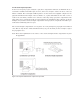
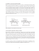
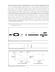
itance value, C, of the capacitor. For example, when the capacitor circuit shown in Figure 5-2 is
measured using the Cs – Rs mode, the displayed capacitance value, Cs, is expressed using the com-
plicated equation shown in Figure 5-3. The Cs value is equal to the C value only when the Rp value
is sufficiently high (Rp >> 1/wC) and the reactance of L is negligible (wL << 1/wC.) Generally, the
effects of L are seen in the higher frequency region where its inductive reactance, wL, is not negligi-
ble. The Rp is usually insignificant and can be disregarded in the cases of high-value capacitors
(because Rp >> 1/wC.) For low-value capacitors, the Rp itself has an extremely high value.
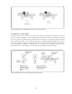
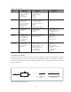
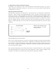
Therefore, most capacitors can be represented by using a series C-R-L circuit model as shown in
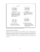
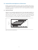
Figure 5-4. Figures 5-5 (a) and (b) show the typical impedance (|Z| _ q) and Cs – D characteristics
of ceramic capacitors, respectively. The existence of L can be recognized from the resonance point
seen in the higher frequency region.
Note: The relationship between typical capacitor frequency response and equivalent circuit model
is explained in Section 1.5.
Figure 5-3. Effects of parasitics in actual capacitance measurement
Figure 5-4. Practical capacitor equivalent circuit
Figure 5-5. Typical capacitor frequency response
C
s
=
–1
–1 - w
2
R
p
2
C
2
w
X
=
w
2
L - w
2
R
p
2
C + w
4
R
p
2
L C
2
C +
=
1 -
R
p
2
C
L
- w
2
LC
w
2
CR
p
2
1
Cs - Rs mode
R
s
L
R
p
C
(a) |Z| - q characteristics (b) C - D characteristics