
User`s guide


212 34980A User’s Guide
8 Microwave Switch/Attenuator Driver
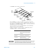
Channel Numbering
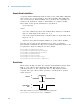
The 34945A uses the following channel numbering scheme:
<slot><rem><channel>
where:
slot is the 34980A slot where the 34945A driver interface is installed,
and is a single digit in the range of 1 to 8.
rem is the remote module being controlled, and is a single digit in the
range of 1 to 8.
channel is the channel number on the remote module.
The channel number is two digits spanning channels across each remote
module. Channel numbers are shown below (also see the figure on
page 209).
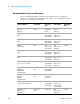
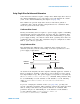
The channel numbers are arranged to facilitate the pairing of channels for
dual coil switches and attenuators. Dual coil devices require the use of
two channels, one for each coil. By pairing the upper and lower channels
in each bank, the devices can be controlled using only the lower channel
number. For example, when a paired- coil device is installed on bank 1,
channels 21 and 31 are paired and are controlled using only channel 21.
For example, the following SCPI command closes channel 5 on the first
remote module connected to a 34945A installed in slot 2.
ROUT:CLOS (@2105)
You can also use a range of channel numbers. You could close all the
channels on the first remote module connected to a 34945A installed in
slot 2 by sending the following command.
ROUT:CLOS (@2101:2178)
Note that when single- coil devices are used, the channel numbering is not
consecutive across all 16 channels in a bank.
Bank Channels Channels
Bank 1 1 to 8 11 to 18
Bank 2 21 to 28 31 to 38
Bank 3 41 to 48 51 to 58
Bank 4 61 to 68 71 to 78