
User`s guide


312 34980A User’s Guide
13 Breadboard Module
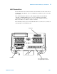
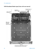
34959A Breadboard Module Description
The 34959A Breadboard Module provides a 137mm x 190mm x 23mm
(5.4” x 7.5” x 0.9”) space inside the 34980A Multifunction Switch/Measure
Unit, for you to install custom circuitry to support applications not
available on the standard plug- in modules.
This module minimizes the need for customer- supplied circuitry by
providing +5V and +12V power supplies for logic and relay drive use,
16 general purpose digital I/O bit lines with control lines, and 32 relay
drive lines. Your custom circuitry can access the 34980A mainframe’s
internal DMM and four Analog Buses. Desired measurement and I/O
functions can be programmed using standard read/write commands.
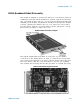
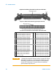
Internally, most of the customer-provided circuitry connects to the module
through two ribbon cables; the Analog Bus connections are made by
hard- soldering to a grid of holes provided on the Agilent- supplied PC
board. Two external ports are provided for Dsub connectors (DB50 or
DB78) between the module and your field wiring.
The sheet metal base of the module provides fifteen countersunk holes for
flexible mounting of circuit boards, terminal blocks or other components.
As with all other plug- in modules for the 34980A, cooling is provided
within the mainframe chassis.
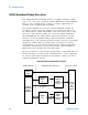
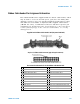
34959A Breadboard Simplified Block Diagram
34959A Breadboard PC Board
Digital
I/O
Custom
Circuitry
and
Field
Wiring
Ribbon
Cable
Connector
(P101)
Ribbon
Cable
Connector
(P102)
Analog Bus
Relays
(4)
34980A
Mainframe
Digital
Backplane
34980A
Analog
Buses
+12V
+5V
34980A Mainframe Custom PC Board
32 Relay Drives
16 Bits