
User`s guide


318 34980A User’s Guide
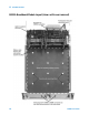
13 Breadboard Module
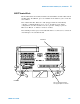
The connections from the Analog Bus outputs (8 holes marked on the
Agilent- supplied PC board as 1 through 4, H and L) to your custom
circuitry should be made with wire insulated for 300V service.
The following table shows which relays must be installed to control the
four Analog Bus channels, and which holes on the Agilent- supplied
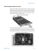
PC board (see the photo on page 317 for the locations to solder each
two- wire output connection):
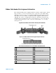
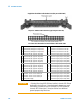
34959A Breadboard: Connections to the 34980A Analog Buses
CAUTION
When soldering wire to the Analog Bus connection holes,
take special care to avoid shorts between wires and/or holes.
Shorting these connections may result in damage to the breadboard
module, the 34980A mainframe, other installed modules, or your test
circuitry.
Relay # Analog Bus Channel Bus # Connect to Hole on PC Board
K101 911 1 1H and 1L
K102 912 2 2H and 2L
K103 913 3 3H and 3L
K104 914 4 4H and 4L
WARNING
SHOCK HAZARD If any of the relays K101-K104 are installed on
the 34959A module’s Agilent-supplied PC board and connections
are made to the Analog Bus output area, hazardous voltages (up to
300V) may be present on the customer’s installed circuit board or
attached test circuitry.
CAUTION
The 34980A mainframe may provide significant current (up to 5A) to
the breadboard before current limits within the mainframe or the
Agilent-supplied PC board activate. Use adequate current limiting
devices (power supply fuses rated at 0.5A are recommended) to
protect the hardware installed on your custom circuit board.