USER’S GUIDE Agilent Technologies Series 661xxA MPS POWER MODULES & Model 66001A MPS KEYBOARD !A Agilent Part No. 5959-3386 Microfiche Part No.
CERTIFICATION Agilent Technologies certifies that this product met its published specifications at time of shipment from the factory. Agilent Technologies further certifies that its calibration measurements are traceable to the United States National Bureau of Standards, to the extent allowed by the Bureau's calibration facility, and to the calibration facilities of other International Standards Organization members.
SAFETY SUMMARY The following general safety precautions must be observed during all phases of operation of this power module. Failure to comply with these precautions or with specific warnings elsewhere in this guide violates safety standards of design, manufacture, and intended use of the power module. Agilent Technologies assumes no liability for the customer's failure to comply with these requirements.
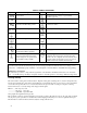
SAFETY SYMBOL DEFINITIONS Symbol Description Symbol Description Direct current Terminal for Line conductor on permanently installed equipment Alternating current Caution, risk of electric shock Both direct and alternating current Caution, hot surface Three-phase alternating current Caution (refer to accompanying documents) Earth (ground) terminal In position of a bi-stable push control Protective earth (ground) terminal Out position of a bi-stable push control Frame or chassis terminal On (
DECLARATION OF CONFORMITY According to ISO/IEC Guide 22 and CEN/CENELEC EN 45014 Manufacturer’s Name and Address Responsible Party Agilent Technologies, Inc. 550 Clark Drive, Suite 101 Budd Lake, New Jersey 07828 USA Alternate Manufacturing Site Agilent Technologies (Malaysia) Sdn.
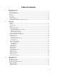
Table of Contents 1. General Information Introduction ..................................................................................................................................................9 Safety Considerations...................................................................................................................................9 Instrument Identification ..............................................................................................................................
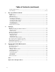
Table of Contents (continued) Module Output Connector .......................................................................................................................29 Error Messages ...................................................................................................................................29-30 4. Basic Power Module Commands Introduction ...........................................................................................................................................
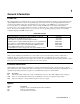
1 General Information Introduction This guide describes how to install, check out, operate, and calibrate the Agilent Series 661xxA power modules used in the Agilent 66000 Modular Power System. Programming the power module from the optional Agilent 66001A Keyboard is described in Appendix B of this guide. Programming the power module over the GPIB bus is covered in the module Programming Guide (see "Related Documents", below). Setting the GPIB address is described in the mainframe Installation Guide.
Accessories Agilent No. 34551A Description Rack mount for Agilent 66001A MPS keyboard Description The Agilent 66lxxA Series Power Modules are used in the Agilent 66000 Modular Power System (MPS) mainframe to provide a range of dc output voltages and currents. The modules are installed or removed from the front of the mainframe without the need for disconnecting any wires. Modules may be connected in series or parallel to provide increased output voltages or currents.
When the power module is operated beyond either rated output, the performance specifications are not guaranteed, although typical performance may be good. Operation in quadrant 2 is limited to about 10% of the maximum rated positive output current. This allows the power module to sink current for more rapid downprogramming in the CV mode. Specifications and Supplemental Characteristics Table 1-1 lists the specifications of the power modules.
Table 1-1. Performance Specifications (continued) Agilent Model Parameter 66101A 66102A 66103A 66104A Line Regulation (change in output voltage or current for any line change within ratings) Voltage: 0.5 mV 0.5 mV 1 mV 2 mV Current: 0.75 mA 0.5. mA 0.3 mA 0.1 mA Transient Response Time (for output < 1 ms voltage to recover to within 100 mV of its previous level following a step change in load current that is up to 10% of the power module rated output current.
Table 1-2. Supplemental Characteristics (continued) Agilent Model Parameter 66101A 66102A 66103A 66104A Temperature Coefficients (change in output per °C after a 30-minute warmup) Output Voltage: 30 ppm + Output Current: 30 ppm + Voltage Readback: 20 ppm + 20 ppm + ± Current Readback: OV Protection: Maximum Reverse Current (maximum current, without damage, that the power module will withstand while turned on and with the dc output reverse biased by an external dc source): 0.1 mV 0.2 mA 0.1 mV 0.
Table 1-2.
Table 1-2. Supplemental Characteristics (continued) Parameter Agilent Model Number and Parameter Value Output Characteristic Curve: Table 1-3. Replaceable Parts List Description Agilent Part No. Cable assembly, mainframe GPIB 0.5 meters (1.6 ft) 10833D 1 meter (3.3 ft) 10833A 2 meters (6.6 ft) 10833B 4 meters (13.
2 Installation Inspection Damage When you receive your power module, inspect it for any obvious damage that may have occurred during shipment. If there is damage, notify the shipping carrier and the nearest Agilent Sales and Support Office immediately. Warranty information is printed in the front of this guide.
Figure 2-1. Power Module Line Fuse and Switches Figure 2-2. Power Module Configuration Switch Table 2-1.
Remote Inhibit (RI) Function Switches This function allows the power module outputs to be shut down from a signal (low-true TTL level) applied to the mainframe INH input. The INH input is internally connected to the mainframe remote inhibit (RI) line. This line is normally high and is distributed to all power modules in the mainframe. An external switch closure that shorts the mainframe INH input is detected by the power module as an RI signal.
Installing The Module In The Mainframe Figure 2-3. Power Module Installation Note 1. 2. 3. 4. 5. 6. A fully loaded mainframe can weigh over 36 kg (80 lbs). Install the mainframe into the rack (see the "Mainframe Users Guide") before installing the modules into the mainframe. Turn off the mainframe power switch. Make certain the pull tab extends from the module (see Figure 2-3). Slide the module into the mainframe slot. You may use any available slot.
Output Connections Before making the actual connections, you must decide on the system configuration. The following factors are described in the rest of this chapter: ■ ■ ■ ■ ■ ■ using the correct wire size maintaining isolation guidelines selecting local or remote voltage sensing connecting modules in series or in parallel using output relays connecting to capacitive or inductive loads Selecting the Proper Wire Size Fire Hazard.
Remote Voltage Sensing Figure 2-4B shows the wiring for remote sensing. There is a switch on the output connector that selects either local or remote sensing of the output voltage. To configure the output for remote sensing, do the following: ■ ■ Connect sense leads to the load Make certain that the connector switch is set to REMOTE Note If you leave the connector switch in LOCAL, the power module will regulate the programmed voltage at the connector, not at the load.
Output Rating The rated output voltage and current specified in Table 1-1 applies at the output terminals of the power module. With remote sensing, the power module must increase its output to compensate for voltage dropped in the load leads. If you attempt to provide full rated output voltage at the sense terminals (load), the power module’s output voltage may exceed its maximum rating.
5. 6. 7. 8. 9. In order to maintain proper regulation, the load must always draw at least as much current as is programmed for the module that is in CC mode. You can maintain regulation over a range of current only as long as this condition remains true. As near as is permitted by condition 5, program the current levels of both modules for a balanced distribution of the total output current. Do not program the CV module near its maximum output current level. Program the outputs of both modules ON.
Figure 2-6. Connecting Power Modules in Series Each power module has a reverse voltage protection diode across its output. If a reverse voltage is applied, the power module has no control over the current through this diode. To avoid damaging the power module, never connect it to a reverse voltage that can force it to conduct current in excess of the power module’s maximum reverse current (see Table 1-2).
The power module is designed to be stable for load capacitances up to the following values: Agilent 66101A Agilent 66102A Agilent 66103A 50,000 µF 20,000 µF 10,000 µF Agilent 66104A Agilent 66105A Agilent 66106A 4,500 µF 2,750 µF 1,650 µF Inductive Loads You may safely connect the power module output to inductive loads up to 100 mH. (Higher inductances are possible with a modified module. Consult the factory for details.
3 Turn-On Checkout Introduction This chapter provides a quick test of the power module functions. See "Chapter 4 - Basic Power Module Commands" for more details of power module operation. Note These procedures assume you have checked and, if required, correctly set the following switches for each module: • the line voltage switch (see Figure 2-1) • the configuration switch (see Table 2-2) • the output connector Local/Remote switch The procedures for doing this are given in Chapter 2.
Power Module Turn-On State When you turn on the mainframe, the power module goes through a self-test. All front panel readout digits and annunciators turn on briefly. The panel then remains in the state shown in Table 3-1A. Note The figure assumes the power module still retains its factory default turn-on state. You can change this state if desired (see "Chapter 4 - Basic Power Module Commands"). Checking Basic Module Functions The power module is designed for remote programming over the GPIB.
In Case Of Trouble Mainframe Failure You can assume there is a problem with the mainframe if there is more than one module in the mainframe and none of the module fans are on. The trouble also is probably in the mainframe if the module fans are on and the their displays are enabled (see "Configuration Switch" in "Chapter 2 - Installation") but their VOLTS and AMPS displays do not light. If a module does not appear to be operating but its VOLTS and AMPS display light, move the module to another address slot.
Selftest Error Messages Table 3-3 lists the displayed selftest error messages. All these errors are hardware failures that require service. Note If you are using the optional Agilent 66001A MPS Keyboard, it will also display selftest error messages. Display U 1 U 2 U 3 U 4 U 5 U 6 U 7 Failed Test Internal RAM External RAM ROM checksum (Not used) (Not used) 12 V supply 5 V supply Table 3-3.
4 Basic Power Module Commands Introduction "Chapter 3 - Language Dictionary" of the Programming Guide describes all the power module commands. This chapter introduces you to the commands that control the following basic functions: • • • • output state protection circuits fixed-mode output list-mode output • • • triggers the RFI function the DFI function The power module can be programmed from a controller over the GPIB or from an optional Agilent 66001A MPS Keyboard plugged into the mainframe.
Controlling the Output State The following commands control the power module output state: Command OUTP ON OUTP OFF OUTP1,NOR OUTP 0,NOR OUTP: REL 1 OUTP:REL 0 OUTP:REL:POL NORM OUTP:REL:POL REV Table 4-1. Power Module Output Commands Function Enables the output. Disables the output. (If an optional output relay is installed, the command is executed in a sequence that prevents "hot switching".) Enables the output without affecting the output relay. Disables the output without affecting the output relay.
Controlling List-Mode Output The following commands control the power module list-mode voltage and current output. Lists require a trigger to begin execution. For an explanation of lists and triggers, see "Chapter 5 - Synchronizing Power Module Output Changes": in the Programming Guide. Table 4-4. Power Module List-Mode Output Commands Command Function CURR:MODE LIST Sets the current mode to list (as opposed to fixed). LIST:CURR , Programs the output current values (or points) in the list.
Using the RI/DFI Functions RI (Remote Inhibit) Input The signal applied to the mainframe digital connector INH input (see "Chapter 3 Connections" of the mainframe Installation Guide) is the RI (remote inhibit). The module function switch described in "Chapter 2 - Installation" allows you to enable or disable the RI input and, when enabled, to specify RI as either latching or nonlatching. If the module function switch is set to enable RI, then the input signal will disable the power module output.
A Calibration Introduction The power module may be calibrated either over the GPIB from a controller or from an Agilent 66001A Modular Power System keyboard. Instructions are included for either method. The procedures given here apply to all Series 66l0xA Power Modules. Note The Agilent 66000A mainframe does not require calibration. Enabling Or Disabling The Calibration Function There are two ways of controlling access to the calibration function. One is by hardware and the other is with software.
Equipment Required The equipment listed in Table A-1, or equivalent, is required for calibration. Equipment Voltmeter Shunt Agilent 66101A, 66102A Agilent 66103A, 66104A, 66105A, 66106A GPIB Controller or Keyboard Table A-1. Equipment Required for Calibration Characteristics D-c accuracy 0.005%, 6 digits; resolution 1 µV 0.01Ω, 100 A, 100 W, 0.04% @ 100 W, 0.01% @ 1W, power coeff. 0.0004%/watt in air 0.1 Ω, 15 A, 25 W, 0.04% @ 25 W, 0.01% @ 1W, power coeff. 0.
Figure A-1. Calibration Test Setup Calibrating Current The following procedure calibrates the output current. During the calibration, you will make two voltage measurements across the output shunt and enter the computed current. Keyboard Entry Table A-3. Current Calibration Procedure Controller Entry † Function OUTP OFF Disable the output Connect the equipment as shown in Figure A-lB. (Before proceeding, set the module output, via the keyboard or the GPIB, for 1.0 V at 0.5 A.
Using The CAL:AUTO Command Normal calibration procedures also calibrate the readback circuits that respond to the MEAS: CURR? and MEAS: VOLT? commands. During normal operation, the readback accuracy is affected by temperature changes within the power module. Use of the CAL:AUTO command reduces the temperature error component of the readback accuracy specification. See "Chapter 3 - Language Dictionary" of the Programming Guide for information about this command.
10 ! VOLTAGE CALIBRATION PROGRAM 20 ! CONNECT INSTRUMENTS AS SHOWN IN FIGURE A-la 30 ! 40 DIM Resp$[255],Err_msg$[255] 50 Volt_cal: ! 60 Err_found=0 70 INPUT "CONNECT INSTRUMENTS AS SHOWN IN FIGURE A-la ... Press any key to continue.
700 710 720 730 740 750 760 770 780 790 800 810 820 830 840 850 860 870 500 INPUT "ENTER VALUE OF CURRENT SHUNT BEING USED",Shunt_val 510 OUTPUT @Ps;"CAL:CURRENT:LEVEL MIN" 520 INPUT "ENTER VOLTAGE MEASUREMENT FROM EXTERNAL VOLTMETER",Volt_read 530 Current=Volt_read/Shunt_val 540 OUTPUT @Ps;"CAL:CURRENT ";Current 550 OUTPUT @Ps;"CAL:CURRENT:LEVEL MAX" 560 INPUT "ENTER VOLTAGE MEASUREMENT FROM EXTERNAL VOLTMETER",Volt_read 570 Current=Volt_read/Shunt_val 580 OUTPUT @Ps;"CAL:CURRENT ";Current 590 GOSUB Save_
B Using The Agilent 66001A MPS Keyboard Introduction This appendix describes the Agilent 66001A Modular Power System (MPS) Keyboard, which is available as an option for the Agilent 66000A Modular Power System. The Agilent 66001A MPS Keyboard lets you program the Agilent 66000A Modular Power System without having to connect it to a computer. With the keyboard, you can: ■ ■ ■ ■ ■ Access any module in the mainframe that the keyboard is plugged into.
Keyboard Description This section briefly explains the various areas on the keyboard as indicated in the following figure: DISPLAY Subaddress and Instrument The subaddress of the presently selected module appears on the left side of the display. The instrument field displays an instrument number when the module contains more than one instrument. Power supply modules do not use this field.
ô SYSTEM KEYS This key switches from remote operation (over the GPIB) to local operation using the keyboard. Press when the Rmt annunciator is on to enable the keyboard. This key moves the cursor to the subaddress field so you can select another module. Use the Entry or Select keys to enter another subaddress. í FUNCTION KEYS This function continuously displays operating information about the selected module.
û ENTRY KEYS These keys let you enter numeric values. Values can be entered directly. If the Meter function is active, the display automatically switches to the Command function with the appropriate command for programming the metered mode on the display. This key enters the decimal point. This key is used to separate multiple command arguments such as those used with a List command. These keys let you increment and decrement the numeric values in the selected field when the Meter function is active.
Using The Display Changing or Entering Values The following figure is an example of the keyboard display when a power module is addressed and the Meter function is active: The keyboard continuously displays measured voltage and current. The blinking cursor initially highlights the voltage field, which indicates that the value in that field can be changed using the numeric Entry keys. You can also use the and keys to move the cursor across the display to select other fields that you want to change.
Sending SCPI Commands As described in the power module Programming Guide, SCPI commands are organized into message units. The keyboard can only send one message unit at a time; you cannot combine message units. Also, optional headers within a command do not appear on the display.
Press to execute the command. Using the letter keys to directly access and send commands is much faster than using the Select keys to find and then send commands. Of course, this method is faster only if you know which commands you are going to program. The following sequence shows the same example using the letter keys: Press to execute the command. Query Example Queries return data from the addressed module.
The query response remains on the display until you press another key to do something else, or until the module goes into remote mode. Press or to return to the meter function. To query the programmed setting of any command parameter, use the cursor control keys to access the parameter field of the command. The value that appears is the last programmed value.
If the Err annunciator is still on after the error message is displayed, it means there are additional error messages in the SCPI error queue. Press to display the other messages. Each time you press the key it removes one error from the error queue. SCPI Command Tree The following figure illustrates the SCPI command tree used by the keyboard.
Agilent 60001A MPS Keyboard
Index A address slot, 20 ampere capacity, 21 annunciators, display panel Addr, 27 CC, 27 Dis, 27 Prot, 27 Unr, 27 C cables GPIB, 15 serial link, 15 calibrating current, 37 calibrating voltage, 36 calibration, 35 constants, 38 equipment for, 36 password, 35, 38 program for, 39 verification of, 35 capacitive loads, 26 CC mode, 11 checkout, output, 28 checksum error, 28 commands (see SCPI) commands, common, 46, 50 commands, subsystem, 46, 50 connector, FLT/INH, 34 connector, output, 21, 22, 25, 29 controller,
Index (continued) Lsn, 42 Prot, 42 Rmt, 42 Shift, 42 SRQ, 42 Tlk, 42 Unr, 42 keyboard cursor, 45 keyboard display, 42, 45 keyboard entry keys, 44, 45 keyboard function keys, 43 keyboard jack, 41 keyboard keys , 44 , 44 , 44 , 44 , 44 , 43, 45, 47 , 43, 45 , 43, 46 , 43, 46, 47 , 44 , 44 , 43, 46, 47 , 43 , 44 , 44, 45, 47, 48 , 43 , 43, 48 , 43, 49 , 43, 48 , 43 , 44 , 43 , 43, 48 , 44, 46 , 44 , 43, 45 , 43 , 44, 45 , 44 keyboard letter keys, 44 keyboard number keys, 44 52 Index keyboard select keys, 43
Index (continued) R remote inhibit (see RI) RI description of , 10 digital connector pins for (see Chapter 3 in Installation Guide) examples of use , 34 example of wiring (see Chapter 3 in Installation Guide) mainframe input signal (see Chapter 5 in Programming Guide) RI Questionable Status bit (see Chapters 3 and 4 in Programming Guide) signal electrical characteristics (see Chapter 1 in Installation Guide) *RST state (see power-on state) recalling states, 28 relay, output, 10, 25, 29 remote sensing, 13, 2
Agilent Sales and Support Offices For more information about Agilent Technologies test and measurement products, applications, services, and for a current sales office listing, visit our web site: http://www.agilent.com/find/tmdir You can also contact one of the following centers and ask for a test and measurement sales representative. United States: Agilent Technologies Test and Measurement Call Center P.O.
Manual Updates The following updates have been made to this manual since the print revision indicated on the title page. 4/15/00 All references to HP have been changed to Agilent. All references to HP-IB have been changed to GPIB. 6/21/02 The serial number and option number information in chapter 1 has been updated. 9/21/04 The Declaration of Conformity has been updated.