
Specifications


Calibration and Preventive Maintenance 103Chapter 6
2. Run the ‘autoadj.tpa’ testplan.
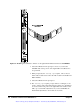
3. When prompted by the ‘autoadj.tpa’ testplan, adjust
potentiometer R196
1
(front panel of the Agilent E6171B module) to
match the indicated reading. See Figure 6-3.
4. Select the OK button in the adjustment box. Note: select the
CANCEL button if you are unable to center the vertical bar.
5. When prompted by the ‘autoadj.tpa’ testplan, adjust
potentiometer R197
1
(front panel of the Agilent E6171B module) to
match the indicated reading. See Figure 6-4.
6. Select the OK button in the adjustment box. Note: select the
CANCEL button if you are unable to center the vertical bar.
7. System adjustment is complete.
1. Potentiometers R196 and R197 are very sensitive. Typically you should rotate the controls only a slight
amount. Rotating clockwise moves the bar to the right, rotating counterclockwise moves the bar to the left.
Artisan Technology Group - Quality Instrumentation ... Guaranteed | (888) 88-SOURCE | www.artisantg.com