SERVICE MANUAL GPIB DC Power Supplies Agilent Series 668xA For instruments with Serial Numbers: Agilent Model 6680A: US36480101 and Agilent Model 6681A: US36400101 and Agilent Model 6682A: US36440101 and Agilent Model 6683A: US36420101 and Agilent Model 6684A: US36410101 and Above * Above * Above * Above * Above * * This manual also applies to instruments with the older serial number format described on page 7. For instruments with higher serial numbers, a change page may be included.
CERTIFICATION Agilent Technologies certifies that this product met its published specifications at time of shipment from the factory. Agilent Technologies further certifies that its calibration measurements are traceable to the United States National Bureau of Standards, to the extent allowed by the Bureau's calibration facility, and to the calibration facilities of other International Standards Organization members.
SAFETY CONSIDERATIONS GENERAL. This is a Safety Class 1 instrument (provided with terminal for connection to protective earth ground). OPERATION. BEFORE APPLYING POWER verify that the product is set to match the available line voltage, the correct line fuse is installed, and all safety precautions (see following warnings) are taken. In addition, note the instrument's external markings described under "Safety Symbols". WARNING. • Servicing instructions are for use by service-trained personnel.
Safety Symbol Definitions Symbol Description Symbol Description Direct current Terminal for Line conductor on permanently installed equipment Alternating current Caution, risk of electric shock Both direct and alternating current Caution, hot surface Three-phase alternating current Caution (refer to accompanying documents) Earth (ground) terminal In position of a bi-stable push control Protective earth (ground) terminal (Intended for connection to external protective conductor.
Table of Contents Introduction ............................................................................................................................................................................ 7 Scope................................................................................................................................................................................... 7 Organization...........................................................................................................
Post-Repair Calibration..................................................................................................................................................... 62 When Required .............................................................................................................................................................. 62 Inhibit Calibration Jumper .....................................................................................................................................
1 Introduction Scope Organization This manual contains information for troubleshooting and repairing to the component level Agilent Series 668xA, 5-kilowatt power supplies. The remaining chapters of this manual are organized as follows: Chapter Chapter 2 Chapter 3 Chapter 4 Chapter 5 Chapter 6 Appendix A Description Verification procedures to determine the performance level of the supply either before or after repair.
Related Documents Change Sheet There may or may not be a Manual Change sheet included with this manual (see Manual Revisions). If one is included, be sure to examine it for changes to this manual. Operating Manual Each power supply is shipped with an operating manual (see Replaceable Parts, Chapter 5 for part numbers) that covers the following topics: • • • • • • • • • • • • Options, accessories, specifications, supplementary characteristics, output characteristic curve, typical output impedance curves.
Safety Considerations This power supply is a Safety Class I instrument, which means it has a protective earth terminal. This terminal must be connected to earth ground through a power source equipped with a 4-wire, ground receptacle. Refer to the "Safety Summary" page at the beginning of this manual for general safety information. Before operation or repair, check the power supply and review this manual for safety warnings and instructions.
2 Verification Introduction This chapter provides test procedures for checking the operation of Agilent Series 668xA power supplies. The required test equipment is specified and sample performance test record sheets are included. Instructions are given for performing the tests either from the front panel or from a controller over the GPIB. Tests Two types of procedures are provided: Operation Verification tests and Performance tests.
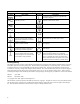
Table 2-1. Test Equipment Required Type Digital Voltmeter1 Required Characteristics Recommended Model Resolution: 10 nV @ 1V Readout: 8 1/2 digits Accuracy: 20 ppm Agilent 6682A, 6683A, Agilent 6684A: 0.001Ω ± 0.04%, 300A, 100W Agilent 3458A Agilent 6680A, 6681A 100 µΩ ± 0.05%, 1000A DC Power Source with current capability equal to UUT Range: Voltage and current range must exceed that of supply under test. Power: 5.4KW minimum or 5 Kilowatt minimum Agilent 6680A = 5.
Programming The Tests General Considerations Procedures are given for programming these tests either from the front panel keypad or from a GPIB controller. The procedures assume you know how to use the front panel keypad or how to program over the GPIB (see the Power Supply Operating Manual for more information). When using computer-controlled tests, you may have to consider the relatively slow (compared to computer and system voltmeters) settling times and slew rates of the power supply.
Operation Verification Tests Table 2-3 lists the requirements for operation verification, which is a subset of the performance tests. Table 2-3.
Figure 2-1.
Table 2-4. Constant Voltage (CV) Tests Action Normal Result Voltage Programming and Readback Accuracy This test verifies that the voltage programming, GPIB readback (GPIB system power supplies only), and front panel display functions are within specifications. With system power supplies, values read back over the GPIB should be the same as those displayed on the front panel. 1 Turn off the power supply and connect a DVM across +S and -S (see Fig. 2-1).
Table 2-4. Constant Voltage (CV) Tests (continued) Action Normal Result CV Source Effect (cont) 2 Set the transformer to the nominal ac line voltage. Connect the DVM across +S and -S (see Fig. 2-1). 3 Turn on the power supply and program the current to its maximum programmable value and the voltage to its full-scale value (see Table 2-2). 4 Adjust the load to produce full-scale current (see Table 2-2) as shown on the front panel display.
Table 2-4. Constant Voltage (CV) Tests (continued) Action Normal Result Transient Recovery Time This test measures the time required for the output voltage to return to within 100mV of its final value following a 50% change in output load current. Measurements are made on both the unloading transient (from full load to 1/2 load) and the loading transient (from 1/2 load to full load). 1 Turn off the power supply and connect an oscilloscope across +S and -S (see Fig. 2-1).
Constant Current (CC) Tests Test Setup Connect the appropriate current monitoring resistor (see Table 2-l) as shown in Fig. 2-3. The accuracy of the resistor must be as specified in the table. Test Procedures The test procedures are given in Table 2-5. The tests are independent and may be performed in any order. The CC tests are: • • • • Current Programming and Readback Accuracy. CC Load Effect. CC Source Effect. CC Noise (PARD). Table 2-5.
Table 2-5. Constant Current (CC) Tests (continued) Action Normal Result CC Noise (PARD) (cont) 2 Measure the residual noise on the DVM with the power supply turned off. Noise generated by other equipment may affect this measurement and should be removed or factored out. 3 Turn on the power supply and program the current to its full scale value and the voltage to its maximum programmable value (see Table 2-2).
Table 2-5. Constant Current (CC) Tests (continued) Action Normal Result CC Source Effect This test measures the change in output current resulting from a change in ac line voltage from its minimum to its maximum value within the line voltage specifications. It is recommended that you use averaged readings for Steps 6 and 8 of this test (see "Averaging AC Measurements" at the end of this chapter) . 1 Turn off the power supply and connect the ac power input through a variable-voltage transformer.
Figure 2-3.
Figure 2-4.
Averaging the CC Measurements The CC Load Effect and CC Source Effect tests measure the dc regulation of the power supply's output current. When doing these tests, you must be sure that the readings taken are truly dc regulation values and not instantaneous ac peaks of the output current ripple. You can do this by making each measurement several times and then using the average of the measurements as your test value.
Table 2-6. Performance Test Record Form Test Facility: __________________________________________ __________________________________________ __________________________________________ __________________________________________ Model_____________________________________ Serial No.__________________________________ Options ____________________________________ Firmware Revision ___________________________ Report No.
Table 2-7. Performance Test Record for Agilent Model 6680A MODEL Agilent _____________ Report No.______________ Test Description Minimum Spec. Results * Date_____________________ Maximum Spec. Measurement Uncertainty Constant Voltage Tests Voltage Programming and Readback Low Voltage (0V) Vout Front Panel Display Readback -5mV Vout - 7.5mV ________mV ________mV +5mV Vout + 7.5mV 1.6 µV 1.6 µV High Voltage (5V) Vout Front Panel Display Readback 4.993V Vout - 10mV _________V _______mV 5.
Table 2-7. Performance Test Record for Agilent Model 6681A MODEL Agilent_____________ Report No.______________ Test Description Minimum Spec. Results * Date_____________________ Maximum Spec. Measurement Uncertainty Constant Voltage Tests Voltage Programming and Readback Low Voltage (0V) Vout Front Panel Display Readback -8mV Vout - 12mV ________mV ________mV +8mV Vout + 12mV 1.6 µV 1.6 µV High Voltage (8V) Vout Front Panel Display Readback 7.988V Vout - 16mV _________V _______mV 8.
Table 2-7. Performance Test Record for Agilent Model 6682A MODEL Agilent_____________ Report No.______________ Test Description Minimum Spec. Results * Date_____________________ Maximum Spec. Measurement Uncertainty Constant Voltage Tests Voltage Programming and Readback Low Voltage (0V) Vout Front Panel Display Readback -21mV Vout - 32mV ________mV ________mV +21mV Vout + 32mV 1.7 µV 1.7 µV High Voltage (21V) Vout Front Panel Display Readback 20.970V Vout -42mV _________V _______mV 21.
Table 2-7. Performance Test Record for Agilent Model 6683A MODEL Agilent_____________ Report No.______________ Test Description Minimum Spec. Results * Date_____________________ Maximum Spec. Measurement Uncertainty Constant Voltage Tests Voltage Programming and Readback Low Voltage (0V) Vout Front Panel Display Readback -32mV Vout - 48mV ________mV ________mV +32mV Vout + 48mV 1.9 µV 1.9 µV High Voltage (32V) Vout Front Panel Display Readback 31.995V Vout - 64mV _________V _______mV 32.
Table 2-7. Performance Test Record for Agilent Model 6684A MODEL Agilent_____________ Report No.______________ Test Description Minimum Spec. Results * Date_____________________ Maximum Spec. Measurement Uncertainty Constant Voltage Tests Voltage Programming and Readback Low Voltage (0V) Vout Front Panel Display Readback -40mV Vout - 60mV ________mV ________mV +40mV Vout + 60mV 2 µV 2 µV High Voltage (40V) Vout Front Panel Display Readback 39.944V Vout - 80mV _________V _______mV 40.
3 Troubleshooting Shock Hazard: Most of the procedures in this chapter must be performed with power applied and protective covers removed. These procedures should be done only by trained service personnel aware of the hazard from electrical shock. This instrument uses components that can be damaged or suffer serious performance degradation due to ESD (electrostatic discharge). Observe standard antistatic precautions to avoid damage to the components (see Chapter 1).
Test Equipment Required Table 3-1. Test Equipment Required Equipment Logic Probe Test Clips Ammeter/Current Shunt Purpose To check states of data lines. To gain access to IC pins. To measure output current. Oscilloscope Signature Analyzer To check waveforms and signal levels. To troubleshoot most of the primary and secondary interface circuits. To communicate with power supply via the GPIB (for system units). To measure output voltage and current, bias and references.
Table 3-2. Selftest Error Codes/Messages Code and/or Message El FP RAM E2 FP ROM E3 EE CHKSM E4 PRI XRAM E5 PRI IRAM E6 PRI ROM E7 GPIB E8 SEC RAM E9 SEC ROM E10 SEC 5V E11 TEMP E12 DACS Description Front panel RAM test failed (power-on). Front panel ROM test failed (power-on and *TST?). Front panel EEPROM checksum test failed (power-on and *TST?). Primary interface external RAM test failed (power-on). Primary interface internal RAM test failed (power-on).
Troubleshooting Charts Figure 3-1 gives overall troubleshooting procedures to isolate the fault to a circuit board or particular circuit (see Figure 3-20 for the location of the circuit boards). These procedures include the use of power-on selftest (Table 3-2) and signature analysis techniques (Table 3-5 through Table 3-7). Some results of Figure 3-1 lead to more detailed troubleshooting charts that guide you to specific components.
Figure 3-1.
Figure 3-1.
Figure 3-1.
Figure 3-1.
Figure 3-2.
Figure 3-3.
Figure 3-4.
Figure 3-5.
Figure 3-5.
Figure 3-6.
Figure 3-7.
Figure 3-8.
Figure 3-9.
Figure 3-10.
Figure 3-10.
Figure 3-11.
Figure 3-11.
Figure 3-12.
CV/CC Status Annunciators Troubleshooting When troubleshooting the CV/CC status annunciators or status readback circuits, first measure the voltage drop across the gating diodes, which are Al0D651 for the CC circuit and Al0D652 for the CV circuit (see A10, Sheet 2). A conducting diode indicates an active (ON) control circuit. This forward drop is applied to the input of the associated status comparator (A10U502) and drives the output low.
Table 3-4. FET Troubleshooting Chart (continued) Procedure Dynamic Troubleshooting Result 1. Turn off the power supply and remove the A3 FET Board with its heat sink assembly. 2. Short the collectors of Q251 and Q253 or Q351 and Q353 by connecting the collector (case) of each transistor to common ( E507) . 3. Connect waveform generator to J200-1 and J200-2. 4. Set generator to produce a 20 kHz, 20V p-p triangular waveform 5.
Figure 3-13.
Signature Analysis Introduction The easiest and most efficient method of troubleshooting microprocessor-based instruments is with signature analysis (SA). This technique is similar to signal tracing with an oscilloscope in linear circuits. Part of the microprocessor memory is dedicated to SA, and a known bit stream is generated to stimulate as many nodes as possible within a circuit.
Test Headers The power supply has two test headers as shown in Figure 3-15, each with a jumper that can be moved to different positions for SA testing and for other functions. To gain access to the headers, remove the power supply top cover. Pins Description Primary Interface Test Connector A2J106 (Systems Supplies Only) 7 and 8 (FLT/INH) Normal operating (and storage) position. DIG CNTL port** is configured for fault indicator (FLT) output and remote inhibit (RI) input .
Table 3-5. Primary Interface SA Test Description: These signatures check some primary interface circuits on the Systems Supply A2 GPIB Board. Valid A2U106 ROM Firmware Revision: A.01.06 Test Setup: See Figure 3-17. 1. Turn off the power supply and remove the top cover. 2. Connect SA jumper of connector J106 on A2 GPIB Board (see Figure 3-15). 3. Connect signature analyzer CLOCK, START, STOP, and GROUND inputs as show in Figure 3-16 . 4.
Figure 3-16.
Figure 3-16. Signature Analysis Connections, (Sheet 2 of 2) Table 3-6. Front Panel SA Test Description: These signatures check front panel microprocessor AlU3. Valid A1U4 ROM Firmware Revision: A.01.07 Test Setup: See Figure 3-17. 1 .Turn off the power supply and remove the top cover. 2. To gain access to A1 Front Panel Board, perform steps 1 and 2 of the disassembly procedure for A1 Front Panel Assembly (see "Disassembly Procedures"). 3.
Table 3-7. Secondary Interface SA Test Description: These signatures check the secondary microprocessor A5U504. Valid A5U504 ROM Firmware Revision: A.01.04 Test Setup: See Figure 3-17. 1. Turn off the power supply and remove the top cover. 2. To obtain a setup that allows access to components and test points on the A5 Control Board, follow the procedure given in Table 3-3 under "A5 Control Board Setup". 3.
Post-Repair Calibration When Required Calibration is required annually and also whenever certain components are replaced. If components in any of the circuits listed below are replaced, the supply must be recalibrated. Note For calibration procedures, see Appendix A of the Operating Manual. Location A10 Control Board Component CV/CC DACs/operational amplifiers, CV/CC control circuit amplifiers, readback DAC/operational amplifier, readback comparators.
EEPROM Initialization EEPROM AlU6 on the A1 Front Panel Board stores the supply's GPIB address, model number, and constants required to program and calibrate the power supply. If either the front panel board or the EEPROM is replaced, the power supply must be reinitialized with the proper constants by running the program listed in Figure 3-18.
10 ! Program to initialize EPROM or move factory preset data in 668xA 20 ! power supplies. 30 ! RE-STORE " INIT_668X" 40 ! Rev A.00.
510 DATA 115,30,20,1,127,.002701,.2,.00042,10.25 520 ! 530 Eprom_data_6684: ! ! EEPROM data for 6684A 540 DATA 93,74,41,0,83,0,29,70,131,0 550 DATA 98,21,4.6,10,50,0,83,255,20,10 560 DATA 6684,87,97,28,93,128,5,255,0,0 570 DATA 1296,6684,0,20,180,20,180,175,33,98 580 DATA 115,30,20,1,127,.002701,.2,.000333,10.234375 590 ! 600 ! 610 INPUT “Input Power Supply model number.
1020 GOSUB Ps_error ! Error if passcode is not "0"! 1030 IF Err THEN 1040 OUTPUT @Ps;"*IDN?" ! Get data from model # location 1050 ENTER @Ps;Idn$ 1060 Model=VAL(Idn$[POS(Idn$,”,”)+1] ) 1070 ELSE 1080 GOTO Start 1090 END IF 1100 ! 1110 OUTPUT @Ps;"CAL:STATE ON,";Model ! Turn on cal mode, passcode = 1120 ! data at model number location 1130 ! 1140 GOSUB Ps_error ! Error if passcode is not same as 1150 ! data at model # location 1160 IF Err THEN 1170 OUTPUT @Ps;"CAL:STATE ON,";Model$[l,4] ! Turn on cal mode, p
1530 CLEAR SCREEN 1540 PRINT "This program should ONLY be completed if your power supply” 1550 PRINT "EEPROM has been replaced or a component that will effect" 1560 PRINT "the calibration AND the alignment of voltage, overvoltage" 1570 PRINT "and current is complete AND unit has passed the performance" 1580 PRINT "test. Enter C to continue, any other key to abort.
2010 IF Err THEN 2020 PRINT "An error occurred during the EEPROM read/write, Check for" 2030 PRINT "programming errors. Initialization data may be incorrect." 2040 STOP 2050 END IF 2060 ! 2070 PRINT "Operation complete. Program stopped." 2080 STOP 2090 ! 2100 Ps_error: ! Error handling subroutine 2110 OUTPUT @Ps;"SYST:ERR?" ! Check for errors 2120 ENTER @Ps;Err 2130 RETURN 2140 ! 2150 END Figure 3-17.
Top Cover 1. 2. Remove the four screws that secure the carrying straps (two TORX 20 screws on each side). These same screws secure the cover to the chassis. Spread the bottom rear of the cover, and then pull the cover backwards towards the rear of the power supply to disengage it from the front panel. Shock Hazard: Hazardous voltage can exist inside the power supply even after it has been turned off.
A4 AC Input Assembly To remove the A4 AC Input Board first remove the GPIB board then disconnect these cables from the following connectors at the GPIB board: 1. 2. 3. 4. 5. 6. 7. Disconnect the cables going to connector J417 and J420. Disconnect the cable going to connector J419. Remove the three (3) fuse assemblies inside rear of power supply to free the wires going to E400, E401, and E402 on the AC Input Board. Remove the holding screw at the center of board just to the left of the 3-phase choke.
A10 Control Assembly Disconnect the cables from the following connectors at the A10 DC RAIL board: 1. 2. 3. 4. 5. Disconnect the ribbon cable going from to the A6 Bias board. This cable connects to J509 on the A10 board but it is easier to disconnect it at the A6 Bias Board. Disconnect cables from connector J507 (phone) and connectors J510, J511, J512, and J513 on the A10 Control Board. At rear of power supply, remove holding screw directly above fan.
A1DSP1 LCD Display 1. 2. Remove the A1 Front Panel Board as described in that procedure. Remove the nuts securing the LCD display to the front panel assembly and remove the LCD and attached ribbon cable (see CAUTION below). (When reinstalling this cable, be sure to line up the cable stripe over the LCD connector pin marked with a square.) The display connector is fragile. When removing the cable from the LCD display, carefully rock the cable connector back and forth while gently pulling it back.
Figure 3-18.
Figure 3-19.
Figure 3-20.
Figure 3-21.
Figure 3-22.
Figure 3-23.
Figure 3-24.
Figure 3-25.
4 Principles Of Operation Introduction Figure 4-3 (at the end of this chapter) is a block diagram showing the major circuits within the power supply. The power supply consists of the following circuits: • • • • • • • • • • A1 Front Panel Board ckts. A2 GPIB ckts. A10 Control Board including the secondary interface ckts, CV/CC control ckts, switching/downprogramming control ckts. Power circuits on the A4 AC Input Board. A3 FET Assembly ckts. A5 DC Rail Board ckts.
A digital control interface on the A2 GPIB Board provides the following power supply functions: • Relay link. • Digital 1/0. • Remote inhibit (INH). • Discrete fault indicator (FLT). An optical isolator IC (U113) isolates the FLT output signal common from the external fault circuit common. The desired digital interface function is selected by placing a jumper in a header (J106) on the A2 GPIB Board.
The Secondary Microprocessor translates serial data received from the A2 board into parallel 12 bit data. The data bus is connected directly to the four DAC/OpAmp circuits. Under control of the lip the selected DAC converts the bus data into an analog signal. The DAC reference circuit (U503, U504) provides a +10V reference for the CV and CC DACs and a -11.6V reference for the readback DAC. Zener VR501 provides a-6.2V reference for the OV Shunt DAC.
any value of load impedance. Switching between CV and CC is done automatically by the CV/CC control circuits at a value of load impedance equal to the ratio of the programmed voltage value to the programmed current value. A low-level CV or CC signal is generated by the applicable status comparator (P/O U502) and returned to the secondary processor to indicate that the corresponding mode, CV or CC, is in effect. In CV mode, an OR gate diode (D652) conducts and the CV loop regulates the output voltage.
A4 AC Input Board The A4 Input Board contains the Inrush-Current Limit relay (K401), Main Power Relay (K402), current-limiting resistors (R407, R408) and open-fuse-detect resistor circuit (R400-R405). On power-on, the current-limit relay (K401) closes allowing the dc rail capacitors to charge under a controlled condition. This applies ac voltage to the A6 Bias Board. After the turn-on initialization period (approximately 10 seconds), the main relay (K402) closes, shorting out the current-limit resistor.
Figure 4-2. 1ST Stage of the FET H-Bridge Configuration Output Circuits The output circuits include the following circuits: • • • • • • • • Chassis mounted components. Two power transformers, T900/T901. Two inductors, L900/L901. Four rectifiers, D900 through D903. Output capacitors. A7 Snubber board mounted to the heat sink. A8 Fast Sense board. A9 Slow/Downprogrammer board and output bus bars.
Figure 4-3.
5 Replaceable Parts INTRODUCTION Chapter Organization This section lists the replaceable electrical and mechanical parts for the Agilent 668xA series power supplies. (Component location diagrams are located in Chapter 6.
How to Order Parts You can order parts from your local Agilent Technologies, Inc. Sales and Support Office (see the list of offices in the back of this manual). When ordering a part, please include the following information: • the Agilent part number • the desired quantity Ref. Desig. • the part description • the model number of the power supply (for example, Agilent 6682A) Table 5-3. Main Chassis, Replaceable Parts Agilent Part No.
Ref. Desig. C907 6680A 6681A 6682A 6683A 6684A C920, 921,922,923,924,925 6682A, 6683A, 6684A D900 6680A, 6681A D900A,B 6682A 6683A, 6684A D901 6680A, 6681A D90lA,B 6682A 6683A, 6684A D902, 903 6680A, 6681A L900, 901 6680A, 6681A 6682A 6683A 6684A L902, 903 L904, 905, 906 Q981, 982 R900 6680A 6681A 6682A 6683A 6684A T900, 901 6680A 6681A 6682A 6683A 6684A Table 5-3. Main Chassis, Replaceable Parts Agilent Part No. Description 0180-4516 0180-4532 0180-4615 0180-4596 0180-4597 CAP 33000uF 7.
Ref. Desig. 92 Replaceable Parts Table 5-3. Main Chassis, Replaceable Parts (continued) Agilent Part No.
Ref. Desig. Ref. Desig. C1 C2 C4 C5 C6,7 C8 C10-12, C14-16 C17 D1,2 L1 J2 J3 J4,5 J6 L1 R1 R2 R23-25,27-30 R37 R38 R39,40 RT1 Table 5-3. Main Chassis, Replaceable Parts (continued) Agilent Part No. Description 1400-0611 CABLE CLAMP (GPIB/FAN) 5080-2299 LABEL REAR PANEL 5080-2413 CRATE ( shipping container ) 5080-2414 SKID ( shipping container ) 5080-2415 FOAM PAD ( shipping container ) 5080-2314 EDGE PROTECTOR 12 inches ( shipping container ) 5080-2315 EDGE PROTECTOR 2.
Ref. Desig. S1 VR16 U3 U4 U6 U8 W3 W5 Y1 Z16 Table 5-4. A1 Front Panel Board, Replaceable Parts (continued) Agilent Part No. Description 3101-3088 Line switch 1902-0950 Diode Zener 4.7V 5 1820-6721 IC MPU 5080-2466 ROM programmed front panel 1818-4792 IC memory 1820-2724 IC SN74ALS573BN 1258-0209 Jumper (J3) 0811-3590 Jumper 0410-2159 Crystal 10 MHz 1902-0950 Diode Zener 4.
Ref. Desig. Table 5-6. A2 GPIB Board, Replaceable Parts (see Note) Agilent Part No.
Ref. Desig.
Ref. Desig. Q301, 302, 303, 304 Q311, 322, 333, 344 Q351, 352, 353, 354 R201 R202 R203 R205 R206 R207 R208 R209 R210 R211, 212 R213, 214, 216, 217 R220, 221 R222 R224, 225 R226 R227 R228 R229 R230 R231 R232 R233 R237 R238 R239 R240 R241, 242 R243 R244 R245 R246 R247 R248 R249 R250 R251 R252 R253 R254 R255 R256 R257 R258 R260, 261 R262 R263, 264, 265 R266 R267 R268 R269 R270 Table 5-7. A3 FET Assembly, Replaceable Parts (continued) Agilent Part No.
Ref. Desig. R271 R272 R273, 274, 275 R277 R301 R302 R303 R304 R305 R306 R307 R308 R309 R310 R311 R312 R313, 314, 316, 317 R320, 321 R322 R324, 325 R326 R327 R328 R329 R330 R331 R332 R333 R337 R338 R339 R340 R341, 342 R343 R354 R355 R356, 357 R360, 361 R362 R363, 364, 365 R366 R367 R368 R369 R370 R371 R372 R373, 374, 375 R377 R378 R379 R380 R381 R382 98 Replaceable Parts Table 5-7. A3 FET Assembly, Replaceable Parts (continued) Agilent Part No. Description 0757-0200 RES 5.62K 1% 0757-0442 RES l0K 1% .
Ref. Desig. R383 R384, 385 T202 T204 T205 T302 T304 U201, 202 U203 U204 U205 U301, 302 U303 U304 U305 Z201, 301 Table 5-7. A3 FET Assembly, Replaceable Parts (continued) Agilent Part No. Description 0757-0442 RES 10K 1% .125W 8159-0005 RES-ZERO OHMS 9100-4350 XFMR-CURRENT 06624-80091 XFMR-PULSE 5080-2238 XFMR-CUR SHARING 9100-4350 XFMR-CURRENT 06624-80091 XFMR-PULSE 1820-8433 PWM I.C. IR2110 1826-1343 IC-VOLTAGE REG TL431CP 1826-0138 IC COMPARATOR LM339N 1826-1475 VOLTAGE COMPTR LT101lCN8 1820-8433 PWM I.
Ref. Desig. C418 C420, 421, 422 C427 D420, 421, 422, 424, 425 DS420, 421 F420 F420 F421 F421 J430, 431 J432 J433 J436, 437, 438, 439 J440 J441 L420, 421 R420, 421, 422 R423, 424, 425,426,427,428 R429, 430, 431,432,433,434 Table 5-9. A5 DC Rail Assembly, Replaceable Parts Agilent Part No. Description ELECTRICAL PARTS 0160-4048 CAP 0.022uF 20% 0160-7606 CAP luF 275V 0160-7743 C-F .047uF 380V 5060-3516 ASSY.-RECTIFIER 1990-0517 LED 2110-1107 FUSE CLIPS 2110-0934 FUSE .
Table 5-10. A6 Bias Assembly, Replaceable Parts (continued) Agilent Part No. Description C823 0180-4131 CAP 4.7uF 35V C824, 825 0180-3298 C-F 2200uF 50V C826 0160-4834 CAP .047uF 10% C827 0180-3587 CAP 1000uF 50V C828 0180-0230 C-F luF 50V C829, 830, 831 0180-4129 CAP luF 35V C841 0180-4397 C-F 100uF 63V C842 0180-4131 CAP 4.7uF 35V C843, 844, 845 0160-4835 CAP .luF 10% 50V C846 0180-4131 CAP 4.
Ref. Desig. R842 R843 R844 R845, 847 R848 R849 R850 R851 R852 R853, 854, 855 R856 R857 R858, 859, 860 R861 R862 R863 R864 R865 R867 R868 R869 R870 R871 R872 R873 R874 R875 R876, 877, 878 R879, 880 T801 T802 U801 U802 U803 U804 U805 U806 U807 U808 U809, 810, 811 U812 U813 Table 5-10. A6 Bias Assembly, Replaceable Parts (continued) Agilent Part No. Description 0698-6360 RES 10K .1% 0757-0472 RES 200K 1% 0698-6977 RES 30K .1% .125 0698-6360 RES 10K .1% 0698-6977 RES 30K .1% .125 0683-3325 RES 3.3K 5% .
Ref. Desig. C910, 911, 912, 913 6680A, 6681A 6682A 6683A 6684A R910, 911, 912, 913 6680A, 6681A 6682A 6683A 6684A R914, 915, 916, 917, 918 6680A, 6681A 6682A 6683A 6684A R919, 920, 921 6680A, 6681A 6682A 6683A 6684A Table 5-11. A7 Snubber Assembly, Replaceable Parts Agilent Part No. Description ELECTRICAL PARTS 0160-0162 0160-6896 0160-4845 0160-6162 CAP .022uF 10% CAP .
Ref. Desig. Table 5-13. A9 Down Programmer/Slow Sense, Replaceable Parts Agilent Part No.
Ref. Desig. C500, 501, 502 C503 C504 C505 C506 C507 C508 C509, 510 C511 C512 C513 C514, 515 C516 C517 C518, 519 C520 C521 C530, 531, 532 C533, 534, 534 C536, 537, 538 C539 C540, 541, 542, 543 C544 C545, 546 C547 C548 6680A, 6681A C556, 560 C561 C562 C563, 564 C565 C566 C567 C568, 569 C570 C571 C572 C573 C574 C575, 576 C577, 578 C579, 580 C581 C583 C584 C585 C586 C587 6680A 6681A 6682A, 683A, 6684A Table 5-14. A10 Control Assembly, Replaceable Parts Agilent Part No.
Ref. Desig. Table 5-14. A10 Control Assembly, Replaceable Parts (continued) Agilent Part No. Description 0160-4799 CAP 2.
Ref. Desig. Table 5-14. A10 Control Assembly, Replaceable Parts (continued) Agilent Part No. Description 0160-4795 CAP 4.7pF 0160-4835 CAP .luF 10% 50V 0160-5410 CAP 3300pF 5% 0160-4805 CAP 47pF 5% l00V 0160-4831 CAP 4700pF 10% 0160-4833 CAP .022uF 10% 0160-7277 CAP 2.2uF 50V 0160-4832 CAP .0luF 10% 0160-5892 CAP 0.
Ref. Desig. R506 R507 R508 R509 R510 R511 R512 R513 R514 R515 R516 R517 R518 R519 R520 R521 R522 R523, 524 R525, 526 R527 R528 R529 R530 R531 R532 R533 R534 R535 R536 6680A 6681A 6682A 6683A 6684A R537 6680A 6681A 6682A, 6683A 6684A R538 6680A, 6681A 6682A 6683A R539 R540 R550, 551, 552 R553, 554 R555 R556 R557 R558, 559 R560, 561, 562, 563 R564, 565, 566, 567 R568, 569 Table 5-14. A10 Control Assembly, Replaceable Parts (continued) Agilent Part No. Description 0757-0289 RES 13.3K 1% 0698-3155 RES 4.
Ref. Desig. R570, 580 R581 R582, 583 R584 R585 R586 R587 R588, 589 R590 R591, 592 R593 R594 R595 R596 R597 R598 R599, 600 R601, 602 R603 R604 R605, 606 R607 R608, 609 R610 6680A 6681A, 6682A 6683A, 6684A R611 R612 R613 R614 R615 R616 R617 R618 R619 R620 6680A, 6681A 6682A 6683A, 6684A R621 6680A, 6681A 6682A 6683A 6684A R622 6680A, 6681A 6682A 6683A, 6684A R623 6680A, 6681A 6682A 6683A 6684A Table 5-14. A10 Control Assembly, Replaceable Parts (continued) Agilent Part No. Description 0757-0424 RES l.
Ref. Desig. Table 5-14. A10 Control Assembly, Replaceable Parts (continued) Agilent Part No. Description 0757-0453 RES 30.
Ref. Desig. R666 6680A 6681A, 6682A 6683A 6684A R667 6680A 6681A 6682A, 6683A 6684A R668 R669 6680A 6681A 6682A 6683A 6684A R670 6680A 6681A, 6682A 6683A, 6684A R671 R672 6680A 6681A, 6682A 6683A, 6684A R673 R674 R675 R677 R678, 679 6680A 6681A, 6682A 6683A, 6684A R680 6680A, 6681A 6682A 6683A 6684A R681 6680A, 6681A 6682A 6683A 6684A R682 6680A 6681A 6682A 6683A, 6684A R683 6680A 6681A 6682A 6683A, 6684A Table 5-14. A10 Control Assembly, Replaceable Parts (continued) Agilent Part No.
Ref. Desig. Table 5-14. A10 Control Assembly, Replaceable Parts (continued) Agilent Part No. Description R684 6680A 6681A 6682A 6683A 6684A R685 6680A 6681A 6682A .
Ref. Desig. Table 5-14. A10 Control Assembly, Replaceable Parts (continued) Agilent Part No. Description R709 6680A 6681A, 6682A 6683A, 6684A R710 6680A 6681A, 6682A 6683A, 6684A R711 R712 R713 R714 R715 R716 R717 6680A, 6681A 6682A, 6683A, 6684A R718 R719 R720 R721 R724 R725 6680A, 6681A 6682A, 6683A, 6684A R726 R727, 728 R729 R730, 731 R732 R733 R734 R738 R741 6680A 6681A 6682A 6683A 6684A R742 R743 R744 R745 RT500 S500 U500 U501, 502 U503 U504 0757-0468 0757-0464 0757-0464 RES 130K RES 90.9K RES 90.
Ref. Desig. U506 U507 U510, 511, 512 U513, 514, 515 U516, 517 U518 U520 U521, 522 U600 U601 U602 U603 U604 U605 U606 U607, 608 U609 U610 U620, 621 U622 U623 U624 Z500 Z501 Z641 Table 5-14. A10 Control Assembly, Replaceable Parts (continued) Agilent Part No.
6 Diagrams Introduction This chapter contains drawings and diagrams for troubleshooting and maintaining Agilent Series 668xA Power Supplies. Unless otherwise specified, a drawing or diagram applies to all models of the series. Wiring connections to external equipment are shown in the Power Supply Operating Manual. Chapter Organization Table 6-1 summarizes the contents of this chapter. Table 6-1.
Table 6-2.
Table 6-3. Test Points TEST POINT No. & Loc. Signal Tested Measurement and Conditions A2 GPIB BOARD J106-4 Primary/chassis ground U101- 1 U101-6 + 5V primary bias PCLR U101-8 PCLR* U110-3 STX U111-6 SRX U119-4 FPRX U119-18 FPTX Connect meter or scope common here. Then make measurements at test points through . + 5V + 0.2V Goes high for approximately 40 ms at power on, then goes low. Held low for approximately 40 ms at power on, then goes high. Primary transmit to secondary serial data line.
Table 6-3. Test Points (continued) TEST POINT No. & Loc. Signal Tested Measurement and Conditions Bias Board (continued) U308-1 U308-5 PREF RESET* U311-7 D317 U311-2 FAN DETECT -25V FAN_PWN +2.5V Held low for approximately 50 ms at power-on, then goes high. +3V +3V +0.6V A3 FET Board Test points through are on the A3 FET Board. Troubleshooting procedures at these points are given under Dynamic Troubleshooting section of the FET Troubleshooting Chart (Table 3-4).
Table 6-3. Test Points (continued) TEST POINT No. & Loc. U600-10 U601-6 U601-3 U604-3 U603-3 U603-13 J511-1,2 U502-14 U501-7 Q602,C U608-7 U630-11 U630-12 D660-AN U502-12 Signal Tested Measurement and Conditions A10 Control Board (continued) DIVIDER CLOCK (Sheet 3) See Figure 6-1 DIVIDER RESET (Sheet 3) See Figure 6-1 ON LATCH CLOCK (Sheet 3) See Figure 6-1 ON LATCH (Sheet 3) See Figure 6-1 PWM_EN (Sheet 3) Held high for approximately 12 seconds at power-on, then goes low. VOS (Sheet 3) +5 ± 0.
Figure 6-1.
Figure 6-2.
Figure 6-3.
Figure 6-4.
Figure 6-5. LED Board, Component and Test Point Location Figure 6-6.
Figure 6-7.
2 3 4 5 6 7 1 8 Figure 6-8.
Figure 6-9.
Figure 6-10.
Figure 6-10.
12 11 10 9 Figure 6-11.
Figure 6-12.
13 14 Figure 6-13.
13 14 Figure 6-14.
19 17 18 16 15 Figure 6-15.
19 Figure 6-16.
17 18 16 15 Figure 6-16.
Figure 6-17.
Figure 6-18.
Figure 6-19. A7 Snubber Board, Component Location Figure 6-20.
Figure 6-21. A8 Fast Sense Board, Component Location Figure 6-22.
Figure 6-23.
Figure 6-24.
45 44 42 41 47 46 48 43 63 53 55 51 50 38 49 37 21 36 22 20 39 40 36 60 62 61 59 54 52 57 58 56 64 Figure 6-25.
21 22 36 20 37 38 63 Figure 6-26.
39 40 64 Figure 6-26.
50 58 54 56 52 57 51 61 59 53 49 60 55 62 65 66 Figure 6-26.
43 39 41 48 42 47 45 46 40 44 Figure 6-26.
A Backdating Manual backdating describes changes that must be made to this manual for power supplies whose serial numbers are lower than those listed in the title page to this manual. Look in the following table and locate your Agilent model. Then look at each serial number listed for this group. If the serial number of your power supply is prior to any of the serial number(s) listed, perform the change indicated in the Change column. Note that, several changes can apply to your supply.
In Table 5-9 A5 DC Rail Board C418, 0.022uF 250VAC "Y" rated P/N 0160-4048 DELETE Fuse Clips, REF F420 & 421 1/4" P/N 2110-0726, qty, 4. ADD Fuse Holder, REF F420 & 421, 5 x 30mm P/N 2110-0689, qty 2. CHANGE F420 & 421, from 0.5A 500V P/N 2110-0934 to 0.5A 500V 5x30mm P/N 2110-0921. CHANGE 3 In Table 5-14 Al0 Control Board C548, 0.1uF 50V P/N 0160-4835. in parallel with RT500. DELETE RT500, P/N 0837-0412. Pins, P/N 0360-1498, qty. 2.
Table A-1. A2 GPIB Parts List Ref Desig. C102-105 C106 C107,108 C109-111,114,115,121 C122 C123 C124 C125 C126,127 C128 C129-134 C135 C136 C138-140 D107-110 D111-114 D115,116 D119,120 F101 J101 J106 J107,108,114,115 L101 P101 Q101 R103 R104 R105 R106 R107 R108 R109 R111,114 R115-117 R118 R119 R120-122 R123 R130-133 R134 R135,136 R137 Agilent Part No.
Table A-1. A2 GPIB Parts List (continued) Ref Desig. TB101 U101 U106 U108 U109 U110,111 U112 U113 U114 U115 U116 U117 U118 U119 U120 U121 VR101 VR102 VR103,104 W101 Y101 Agilent Part No.
Figure A-1.
Index A A1 Front Panel Board, test header .............................................................................................................................. 57 A2 GPIB Board, test header........................................................................................................................................ 57 A3 FET Board dynamic troubleshooting......................................................................................................................................
CV source effect, defined............................................................................................................................................ 17 CV source effect, testing ............................................................................................................................................. 17 CV transient response waveform ................................................................................................................................
UART PARITY ................................................................................................................................................... 35 error message, selftest ................................................................................................................................................. 35 errors calibration ............................................................................................................................................................
Mnemonics signal names .......................................................................................................................................... 140 mutual coupling, test lead ........................................................................................................................................... 14 N noise, testing ...............................................................................................................................................................
load ...................................................................................................................................................................... 12 resistor, current monitor .............................................................................................................................................. 12 resistor, current monitoring.........................................................................................................................................
Troubleshooting test points ........................................................................................................................................................... 142 troubleshooting chart output held high ................................................................................................................................................... 36 OV at turn-on ........................................................................................................................