Infiniium User’s Quick Start Guide Agilent Technologies
User’s Quick Start Guide Publication number D8104-97003 January 2006 © Copyright Agilent Technologies 2005-2006 All Rights Reserved Infiniium Oscilloscopes
In This Book This book gives you the information you need to begin using the Infiniium Oscilloscopes. It contains four chapters: Setting up the Oscilloscope Chapter 1 contains inspection, power requirements, air flow, and setup information. Working in Comfort Chapter 2 contains recommendations for working comfortably and safely while operating the Infiniium Oscilloscope.
Contents 1 Setting Up the Oscilloscope To inspect package contents 1-3 To inspect options and accessories 1-6 To connect power 1-11 To connect the mouse, the keyboard, a LAN cable, a USB device, a printer, and a GPIB cable 1-15 To connect oscilloscope probes 1-17 To connect SMA Cables 1-20 To connect the digital probe 1-21 Digital probe lead set 1-22 To tilt the oscilloscope upward for easier viewing 1-26 To turn on the oscilloscope 1-27 To turn off the oscilloscope 1-28 To verify basic operation for the 8
Contents To select a command from the menu bar 3-33 To select a command from a context-sensitive menu 3-34 To start and stop waveform acquisition 3-37 To clear the waveform display 3-38 To print the screen 3-39 To change waveform brightness 3-40 To turn a channel on or off 3-41 To adjust the vertical offset 3-42 To adjust vertical scaling 3-44 To access the channel setup 3-45 To set the horizontal reference point 3-46 To adjust sweep speed 3-47 To adjust horizontal position 3-48 To access the horizontal se
1 Setting Up the Oscilloscope
Setting Up the Oscilloscope This chapter shows you how to set up your Infiniium oscilloscope, connect power and accessories, and verify general operation.
Setting Up the Oscilloscope To inspect package contents To inspect package contents ❏ Inspect the shipping container for damage. Keep a damaged shipping container or cushioning material until you have inspected the contents of the shipment for completeness and have checked the oscilloscope mechanically and electrically. ❏ Verify that you received the following items in the Infiniium Oscilloscope packaging.
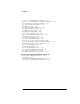
Setting Up the Oscilloscope To inspect package contents Figure 1-1 Infiniium Oscilloscope with Accessory Pouch Front Panel Cover SMA to Precision BNC Adaptors (2) Probe Deskew and Performance Verification Kit Keyboard Calibration Cable Mouse User’s Quick Start Guide Package Contents for the 80000B Series Infiniium Oscilloscopes 1-4 Touchscreen Stylus
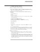
Setting Up the Oscilloscope To inspect package contents Figure 1-2 Infiniium Oscilloscope with Accessory Pouch Front Panel Cover Keyboard 10073C Probe Digital Probe (MSO models only) Mouse User’s Quick Start Guide Touchscreen Stylus SMT IC Clip (MSO models only) Digital Clip Leads (MSO models only) Ground Lead (MSO models only) Package Contents for the 8000A Series Infiniium Oscilloscopes 1-5
Setting Up the Oscilloscope To inspect options and accessories To inspect options and accessories ❏ Verify that you received the options and accessories you ordered and that none were damaged. If anything is missing, contact your nearest Agilent Technologies Sales Office. If the shipment was damaged, or the cushioning materials show signs of stress, contact the carrier and your Agilent Technologies Sales Office.
Setting Up the Oscilloscope To inspect options and accessories Agilent Model Number Description E2697A High Impedance Adapter (includes one 10073C passive probe) 54006A 6 GHz probe, 10:1 (500 Ω) or 20:1 (1 kΩ), .
Setting Up the Oscilloscope To inspect options and accessories Some accessories that will enhance your work with the 8000A series oscilloscopes are listed in table 1-2. Table 1-2 Accessories for the 8000A Series Infiniium Oscilloscopes Agilent Model Number Description 10070C 20 MHz, 1:1, 1 MΩ Passive Probe 10073C 500 MHz, 10:1, 2.
Setting Up the Oscilloscope To inspect options and accessories Agilent Model Number Description E2643A Wedge Adapter, 0.5 mm spacing, 16 signals E2644A Wedge Adapter, 0.65 mm spacing, 16 signals E2614A Wedge Adapter, 0.5 mm spacing, 8 signals E2615A Wedge Adapter, 0.65 mm spacing, 3 signals E2615B 2 Wedge Adapters, 0.65 mm spacing, 3 signals E2616A Wedge Adapter, 0.65 mm spacing, 8 signals E2613A Wedge Adapter, 0.5 mm spacing, 3 signals E2613B 2 Wedge Adapters, 0.
Setting Up the Oscilloscope To inspect options and accessories Acquisition memory upgrades are available to protect your Infiniium oscilloscope investment when acquisition memory needs change. You can install memory upgrades without opening the oscilloscope case or requiring onsite service. Acquisition memory upgrades are listed in table 1-3.
Setting Up the Oscilloscope To connect power To connect power 1 Position the oscilloscope where it will have sufficient clearance for airflow around the top, back, and sides. 2 Position the oscilloscope so that it is not difficult to unplug the power cord.
Setting Up the Oscilloscope To connect power 3 Connect the power cord to the rear of the oscilloscope, then to a suitable ac voltage source (100 to 240 VAC ±10%, 47 to 63 Hz all models for the 8000A series and 100 to 240 VAC ±10%, 47 to 63 Hz for the 80000B series) Maximum power dissipation: 80000B series is 550 W and 8000A series is 440 W. Figure 1-4 Infiniium Oscilloscope Power Cord Connection The oscilloscope power supply automatically adjusts for line input voltages in the range 100 to 240 VAC.
Setting Up the Oscilloscope To connect power Table 1-4 Power Cords Plug Type Part No. Option No.
Setting Up the Oscilloscope To connect power Plug Type 1-14 Part No. Option No.
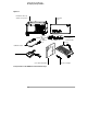
Setting Up the Oscilloscope To connect the mouse, the keyboard, a LAN cable, a USB device, a printer, and a GPIB cable To connect the mouse, the keyboard, a LAN cable, a USB device, a printer, and a GPIB cable See Figure 1-5 for the location of the connectors. Mouse Plug the mouse into the matching connector on the back panel of the oscilloscope. The connectors are labeled 1 and 5.
Setting Up the Oscilloscope To connect the mouse, the keyboard, a LAN cable, a USB device, a printer, and a GPIB cable Figure 1-5 6 3 1 2 7 Back Panel 1-16 4 5 5
Setting Up the Oscilloscope To connect oscilloscope probes To connect oscilloscope probes There are optional Infiniium oscilloscope probes, such as the 1130 and 1160 series probes, that connect to the oscilloscope differently than other oscilloscope probes. Use the following steps to connect these snap-on probes to the oscilloscope. 1 Attach the probe connector to the desired oscilloscope channel or trigger input. Push it straight on until it latches into place.
Setting Up the Oscilloscope To connect oscilloscope probes 2 Connect the probe to the circuit of interest using the browser or other probing accessories. Figure 1-7 Probing the Circuit 3 To disconnect the probe, push the small latch on top of the probe connector to the left, then pull the connector body away from the front panel of the oscilloscope without twisting it.
Setting Up the Oscilloscope To connect oscilloscope probes Figure 1-8 Disconnecting the Oscilloscope Probe CAUTION Do not attempt to twist the snap-on probes on or off the oscilloscope’s BNC connector. Twisting the probe connector body will damage it. CAUTION ! For the 8000A series oscilloscopes do not exceed the maximum input voltage rating. The maximum input voltage for 50 Ω inputs is 5 Vrms, CAT I. Maximum voltage at 1 MΩ impedance is ±100 V (dc + ac) [ac < 10 kHz], CAT I.
Setting Up the Oscilloscope To connect SMA Cables To connect SMA Cables You can connect an SMA cable to the 80000B series Infiniium oscilloscopes by using the 54855-67604 SMA to precision BNC adaptor. 1 Attach the two SMA to precision BNC adaptors to the ends of an SMA cable. 2 Push the SMA to precision BNC adaptors onto the oscilloscope BNC connectors. 3 Tighten the thumbscrews until they are snug.
Setting Up the Oscilloscope To connect the digital probe To connect the digital probe The MSO (Mixed Signal) series oscilloscopes are the only oscilloscopes that have tightly integrated 16 digital timing channels. The digital flying lead marked clk (clock) is unused. All the other digital flying leads are used for the digital timing channels. 1 Push the small connector end of the digital cable with the tab key facing left into the digital connector. 2 Tighten both thumb screws.
Setting Up the Oscilloscope Digital probe lead set Digital probe lead set The MSO (Mixed Signal) oscilloscopes have tightly integrated16 digital timing channels. The digital flying lead marked clk (clock) is unused. All the other digital flying leads are used for the digital timing channels. The flying lead set has 16 digital channels with a ground lead for each channel. Figure 1-11 Digital Flying Lead Set If a 0.63 mm square pin or a 0.
Setting Up the Oscilloscope Digital probe lead set Figure 1-12 250 Ω 90.9 kΩ Signal To Oscilloscope 8.2 pF Probe Tip Isolation Network The loading effect of the probe tip on the circuit under test is represented by the circuit shown in the equivalent load schematic in Figure 1-13. Figure 1-13 370 Ω Signal 1.5 pF 7.
Setting Up the Oscilloscope Digital probe lead set Direct connection through 40-pin connector The probe cable can also be directly plugged into various 40-pin connectors on the circuit board under test. This requires each signal pin of the 40-pin connector to have an isolation network (Figure 1-12) on the circuit board. The pinout of the 40-pin connector is shown in Figure 1-14.
Setting Up the Oscilloscope Digital probe lead set For more information on digital probing solutions, search for the document titled “Probing Solutions for Logic Analysis Systems” (Agilent part number 5968-4632E) on the Agilent Technologies web site at www.agilent.com. The MSO probe cable is fully compatible with various 40-pin connector probes, such as Mictor and Soft Touch.
Setting Up the Oscilloscope To tilt the oscilloscope upward for easier viewing To tilt the oscilloscope upward for easier viewing 1 Lift up the front of the oscilloscope, grasp the wire bail near the center, and pull it down and forward until it latches into place.
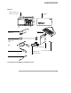
Setting Up the Oscilloscope To turn on the oscilloscope To turn on the oscilloscope The first time that you turn on the oscilloscope, you will need to have a mouse connected. The mouse is needed to accept the Microsoft end-user license agreement for Windows XP Pro. 1 Depress the power switch in the lower left-hand corner of the oscilloscope front panel. Figure 1-16 Turning on the Oscilloscope After a short initialization period, the oscilloscope display appears. The oscilloscope is ready to use.
Setting Up the Oscilloscope To turn off the oscilloscope To turn off the oscilloscope 1 Momentarily depress the power switch at the lower left-hand corner of the oscilloscope front panel. The oscilloscope will go through a normal Windows shutdown process.
Setting Up the Oscilloscope To verify basic operation for the 80000B series oscilloscope To verify basic operation for the 80000B series oscilloscope 1 Connect one end of the calibration cable using SMA to precision BNC adaptors to channel 1. 2 Connect the other end of the calibration cable using the SMA to precision BNC adaptor to the Aux Out connecter on the front panel. Figure 1-17 Calibration Output Verifying Basic Oscilloscope Operation for 80000B Series Oscilloscopes.
Setting Up the Oscilloscope To verify basic operation for the 80000B series oscilloscope 6 Touch the pointer of the touch screen sylus to the surface of the screen and move it around while verifying that the pointer follows the movement.
Setting Up the Oscilloscope To verify basic operation for the 8000A series oscilloscope To verify basic operation for the 8000A series oscilloscope 1 Connect a passive probe to channel 1. 2 Attach the passive probe to the calibration output on the front panel of the oscilloscope. Use a probe grabber tip so you do not need to hold the probe. The calibration output is marked with a square wave symbol. Figure 1-18 Calibration Output Verifying Basic Oscilloscope Operation for 8000A Series Oscilloscopes.
Setting Up the Oscilloscope To verify basic operation for the 8000A series oscilloscope 5 Move the mouse around the mouse surface and verify that the on screen pointer follows moves with the mouse movement. 6 Touch the pointer of the touch screen stylus to the surface of the screen and move it around while verifying that the pointer follows the movement.
Setting Up the Oscilloscope Installing application programs on Infiniium Installing application programs on Infiniium Infiniium is an open Windows system. This allows you to install your own application software. Agilent has verified that the following applications are compatible with the Infiniium oscilloscope application.
Setting Up the Oscilloscope Changing Windows System Settings Changing Windows System Settings Before changing any Windows System settings outside of the oscilloscope application you should Exit the oscilloscope application. There are several Windows System settings that can be changed to suit your own personal preferences. However, there are some system settings that you should avoid changing because it will interfere with the proper operation of the oscilloscope. • Do not change the Power Options.
Setting Up the Oscilloscope To clean the oscilloscope To clean the oscilloscope • Clean the oscilloscope with a soft cloth dampened with a mild soap and water solution. CAUTION Do not use too much liquid in cleaning the oscilloscope. Water can enter the Infiniium front panel, damaging sensitive electronic components.
1-36
2 Working in Comfort
Introduction To optimize your comfort and productivity, it is important that you set up your work area correctly and use your Infiniium oscilloscope properly. With that in mind, we have developed some set-up and use recommendations for you to follow based on established ergonomic principles. Improper and prolonged use of keyboards and input devices are among those tasks that have been associated with repetitive strain injury (RSI) to soft tissues in the hands and arms.
Working in Comfort About Repetitive Strain Injury About Repetitive Strain Injury What is RSI? What causes RSI? What if I experience discomfort? Because your comfort and safety are our primary concern, we strongly recommend that you use the Infiniium oscilloscope in accordance with established ergonomic principles and recommendations.
Working in Comfort Mice and Other Input Devices Mice and Other Input Devices Various aspects of using mice and other input devices may increase your risk of discomfort or injury. Observing the following recommendations may reduce that risk. • Try to keep your hand, wrist, and forearm in a neutral position while using your mouse or other input device.
3 Using the Oscilloscope
Using the Oscilloscope The Infiniium Oscilloscope is designed to be easy to use. • The familiar front-panel oscilloscope interface with knobs and keys is optimized for the most common kinds of troubleshooting tasks and basic measurements. See “Using the Front Panel” on page 3-3. • The graphical interface with menus, windows, dialogs, and toolbars provides easy logical access to dozens of configuration and analysis tools, making it easy for you to set up and make the most complex measurements.
Using the Oscilloscope Using the Front Panel The Infiniium Oscilloscope front panel has been designed to give you direct access to the functions needed to perform the most common measurements needed in troubleshooting, using a traditional oscilloscope interface. Knobs and keys are included to enable direct setting of vertical and horizontal parameters.
Using the Oscilloscope Front Panel Front Panel Figure 3-1 shows a typical Infiniium oscilloscope front panel. Figure 3-1 Horizontal controls Marker and Measurement Controls Power Switch Acquisition and general controls Trigger controls Vertical controls Infiniium Oscilloscope Front Panel Using the front panel, you can configure the Infiniium oscilloscope for most troubleshooting tasks.
Using the Oscilloscope Acquisition and General Controls Acquisition and General Controls Using the acquisition and general controls, you control whether the oscilloscope is running or stopped. Other keys allow you to reset the oscilloscope to its default setup, automatically configure the oscilloscope for the current input signals (Autoscale), or clear the waveforms from the display and reset such things as measurement statistics and averaging.
Using the Oscilloscope Marker and Measurement Controls Marker and Measurement Controls Using the marker and measurement controls, you control two sets of markers within the oscilloscope graticule. You use markers to make more accurate measurements of waveform events than you could make visually. Both time and voltage differences between the markers are updated continuously on the screen. By default, the markers track the source waveform.
Using the Oscilloscope To set the oscilloscope to a known starting condition To set the oscilloscope to a known starting condition • Press the Default Setup key. You can set up the oscilloscope for many different kinds of complex measurements. To easily reset the oscilloscope to a known measurement configuration, use the Default Setup key. If you use the Default Setup key, you can select Undo Default Setup from the Control menu to return the oscilloscope to its original configuration.
Using the Oscilloscope To start and stop waveform acquisition To start and stop waveform acquisition • To start waveform acquisition, press the Run key. The oscilloscope begins acquiring data. When it receives a trigger signal, it finishes acquiring data, updates the display, then starts another acquisition cycle if it is in triggered or auto trigger mode. If it is in single sweep mode, it stops after updating the display. • To stop waveform acquisition, press the Stop key.
Using the Oscilloscope To clear the waveform display To clear the waveform display • Press the Clear Display key. The oscilloscope clears the waveform display. If the oscilloscope is in Run mode and is receiving triggers, it will update the display as it collects new waveform data. Clearing the waveform display also resets averaging, infinite persistence, and color grade persistence, histogram, mask testing database, and measurement statistics.
Using the Oscilloscope To turn an analog channel on or off To turn an analog channel on or off • To turn an analog channel on, press the channel number key until it is illuminated. To turn it off, press the channel number key again. If you are not using a particular channel, you can turn it off. This simplifies the waveform display and also increases the display update rate. While a channel is turned off, data acquisition continues for that analog channel.
Using the Oscilloscope To turn digital channels on or off To turn digital channels on or off Digital channels are only available on the MSO series oscilloscopes. • To turn digital channels on, press the digital channel number key until it is illuminated. To turn them off, press the digital channel number key again. The only digital channels that are displayed are the ones that are turned on in the Digital Setup dialog box.
Using the Oscilloscope To change input impedance and input coupling To change input impedance and input coupling Input impedance and input coupling are only available on the 8000A series oscilloscopes. • To change the input impedance, press the Input key until the LED for the desired impedance is illuminated. Choices are 50 Ω and 1 MΩ. An identified active or passive probe automatically sets the proper input impedance.
Using the Oscilloscope To adjust analog channel’s vertical scale and offset To adjust analog channel’s vertical scale and offset • To make the waveform bigger, turn the vertical scale knob clockwise. To make it smaller, turn the knob counter-clockwise. The vertical scale knob is the larger of the two knobs for a channel. It is marked with a set of sine wave symbols. Decreasing the vertical scale makes the waveform bigger. There are fewer volts displayed per division.
Using the Oscilloscope To adjust digital channel’s vertical size and offset To adjust digital channel’s vertical size and offset Digital channels are only available on the MSO series oscilloscopes. • To select the digital channel which is affected by the vertical offset knob, turn the select knob clockwise to move toward the top-most digital channel. Turn the knob counter-clockwise to move toward the bottom most digital channel. • To make the waveform bigger or smaller, press the size button.
Using the Oscilloscope To adjust sweep speed and horizontal position To adjust sweep speed and horizontal position • To stretch the waveform horizontally, turn the sweep speed knob clockwise. To shrink it horizontally, turn the knob counter-clockwise. The sweep speed knob is the larger of the two horizontal control knobs. It is marked with a set of sine wave symbols. Stretching the waveform means there are fewer seconds displayed per division.
Using the Oscilloscope To magnify a part of the waveform using delayed sweep To magnify a part of the waveform using delayed sweep • To turn on the delayed sweep, press Delayed. To turn it off, press Delayed again. The waveform display area splits into two regions. The top one is the main sweep. The bottom is the delayed sweep, which represents a software expansion of the acquired waveform data.
Using the Oscilloscope To set the oscilloscope to trigger on an edge To set the oscilloscope to trigger on an edge 1 Press and release the Mode key until the Edge LED indicator is illuminated. 2 Press and release the Source key until the desired source LED is illuminated. You can choose any of the channels or the Aux Trig In as the source for an edge trigger. 3 Press the Slope key until the desired slope LED is illuminated. You can have an edge trigger on a rising or falling edge.
Using the Oscilloscope To set the oscilloscope to trigger on an edge Figure 3-12 Set trigger level Select Edge mode Select the trigger source Select rising or falling edge for the Select Trig’d Single, or Auto trigger Trigger Controls and Indicators for 8000A Series Oscilloscopes 3-18 Set the coupling characteristics for the trigger (8000A series oscilloscopes)
Using the Oscilloscope To use the markers To use the markers Markers make it easier to make precise measurements because the marker measurement readouts show exact voltage and time positions for the markers. The measurements are based on actual waveform data from the acquisition system, not on approximations based on the display position, so you can be sure that the values are highly accurate. • To turn on Marker A, press the Marker A key. Marker A has a solid line pattern on the waveform display.
Using the Oscilloscope To use the quick measurements To use the quick measurements • To turn on the quick measurement display, press the QuickMeas+ key. The five preset measurements defined in the Quick Measurement configuration are enabled and results are displayed on the screen for the first waveform source. The default measurements are: Vp-p, Period, Frequency, Rise time, and Fall time.
Using the Oscilloscope To reinitialize the oscilloscope To reinitialize the oscilloscope When you need to restore the oscilloscope to a known configuration, use the Default Setup key. If you press the Default Setup key and the oscilloscope does not seem to be functioning properly, try cycling power. If the oscilloscope still does not seem to function properly, use the following key-down powerup procedure. 1 Turn off the power to the oscilloscope. 2 Turn on the power to the oscilloscope.
Using the Oscilloscope Using the Graphical Interface With the graphical interface for the Infiniium Oscilloscope, you can access all the configuration and measurement features of the oscilloscope through an easy-to-use system of menus, tool bars, dialog boxes, icons, and buttons.
Using the Oscilloscope Graphical User Interface Graphical User Interface The graphical interface looks like the following two figures.
Using the Oscilloscope Graphical User Interface Figure 3-17 See more measurements Turn off any measurements that are running (use Clear display to reset/restart measurement statistics) Run Stop Clear display Print screen Set sweep speed Access the Horizontal Setup dialog box Set horizontal position (delay) Access the Trigger Setup dialog box Set trigger level Waveform Brightness Infiniium Oscilloscope Bottom of Display To make it easy to see which controls affect each waveform, the oscilloscope use
Using the Oscilloscope Graphical User Interface particular measurement situation. For example, it might be easiest to set a coarse vertical scale using the knobs, then fine-tune the setting using the graphical user interface. The graphical interface is arranged so that the most common functions affecting the waveform display are located around the edge of the waveform viewing area. These include the measurement toolbar, horizontal and trigger toolbar, and vertical toolbar.
Using the Oscilloscope Graphical User Interface Other Measurement Features There are more measurements available than will fit on a single toolbar. Click the More (1 of 2) or More (2 of 2) icons to see other measurements. Clicking Clear All will remove all selected measurements from the waveform display area. Tab Display Area The tab display area is located beneath the waveform viewing area.
Using the Oscilloscope Graphical User Interface See “To zoom on a section of the waveform” on page 3-50. Avoid Overdriving Vertical Input Amplifiers When zooming on a waveform with the oscilloscope running, be careful to keep the signal within the screen vertically to avoid overdriving the vertical input amplifiers. Overdriving causes waveform distortion and erroneous measurement results.
Using the Oscilloscope Graphical User Interface Horizontal and Trigger Toolbar At the bottom of the waveform display area is the horizontal and trigger toolbar. This includes the run/stop controls, the horizontal controls, and the trigger controls. Run/Stop Controls See figure 3-24. At the left side of the bar are four icons: • The leftmost is a blue-green octagon. Clicking on this starts an acquisition. (Same as pressing the Run key on the front panel.) • The next control is a red octagon.
Using the Oscilloscope Graphical User Interface The horizontal position value represents the time relative to the trigger at the respective horizontal reference. When you change the horizontal sweep speed, the waveforms expand and contract about this reference position. Trigger settings and controls The right side of the bar contains the trigger settings and controls. These will vary depending on the current trigger configuration, which can be set using the front panel and the graphical interface.
Using the Oscilloscope To perform basic user interface operations To perform basic user interface operations • To move the pointer on the screen, move the mouse or touch the screen with the stylus and move it. • To click on an item in the graphical interface, point at that item with the pointer, then press and release the left mouse button or touch screen. • To right-click on an item in the graphical interface, point at that item with the mouse pointer, then press and release the right mouse button.
Using the Oscilloscope To perform basic user interface operations Figure 3-19 Click and drag the title bar to move the dialog box on the screen Click to put a check mark in the check box and enable Connect Dots mode Click one of these Close buttons to close the dialog box click one of these radio buttons to change the number of waveform viewing areas Click one of these check boxes to select Color Grade or Infinite persistence Click and drag the Intensity control slider up to increase the waveform bright
Using the Oscilloscope To perform basic user interface operations Figure 3-20 Click the arrow in a drop-down list box... ...
Using the Oscilloscope To select a command from the menu bar To select a command from the menu bar 1 Click on a menu bar item. 2 Move the pointer to the desired menu item. 3 Click the mouse button or touch screen. The desired command is executed, or a dialog box is presented for you to configure the oscilloscope. If you continue to hold the mouse button after step 1, release the button in step 3 to execute the command. Some menus have submenus.
Using the Oscilloscope To select a command from a context-sensitive menu To select a command from a context-sensitive menu 1 Move the mouse pointer to a particular area of the display in which you want to change the oscilloscope configuration. Context-sensitive menus provide quick access to commands and configuration items that relate only to the context of the particular graphical interface item in which they are found.
Using the Oscilloscope To select a command from a context-sensitive menu Figure 3-22 Right-click the mouse in the waveform display area, then select Autoscale from the menu to force the oscilloscope to autoscale the current waveform(s) Selecting a Command from a Context-Sensitive Menu 3-35
Using the Oscilloscope To select a command from a context-sensitive menu Figure 3-23 Right-click in this region to see the Acquisition Setup context-sensitive menu Right-click in this region to see the Measurement Setup context-sensitive menu Right-click in the waveform display area to see the waveform contextsensitive menu Right-click in this region to see the horizontal, trigger, and run controls context-sensitive menu Location of Context-Sensitive Menus 3-36 Right-click in this region to see the co
Using the Oscilloscope To start and stop waveform acquisition To start and stop waveform acquisition • To start waveform acquisition, click the start button at the bottom of the waveform display area. • To stop waveform acquisition, click the stop button at the bottom of the waveform display area. See figure 3-24. You can still use the Run and Stop keys on the front panel.
Using the Oscilloscope To clear the waveform display To clear the waveform display • Click the clear display button at the bottom of the waveform display. See figure 3-25. You can still use the Clear Display key on the front panel while the graphical interface is enabled. Clearing the display removes all displayed waveform data in preparation for another acquisition. It also resets all automatic measurements and measurement statistics.
Using the Oscilloscope To print the screen To print the screen • Click the print button at the bottom of the waveform display. See figure 3-26. Infiniium prints the screen to the default printer according to the configuration that you have selected in the Windows Control Panel.
Using the Oscilloscope To change waveform brightness To change waveform brightness • Click the waveform brightness button at the bottom of the waveform display. See figure 3-27.
Using the Oscilloscope To turn a channel on or off To turn a channel on or off • To turn a channel on, click the check box next to the channel number so that a check mark appears in the box. To turn a channel off, click the check box again to clear it. See figure 3-28. If you are not using a channel, you can turn it off. This simplifies the waveform display and also increases the display update rate.
Using the Oscilloscope To adjust the vertical offset To adjust the vertical offset • Click and hold the left mouse button or touch screen stylus on the waveform you want to move, then drag the pointer up or down to move the waveform to the desired offset. Release when finished. or • Click and hold the left mouse button or touch screen stylus on the ground reference indicator for the waveform you want to move, then drag the pointer to move the waveform to the desired offset. Release when finished.
Using the Oscilloscope To adjust the vertical offset Figure 3-29 Click to access the Channel Setup dialog, then set vertical offset using the spin box or numeric keypad... ...or click on the ground reference indicator and drag it up or down to change the vertical offset... ...or click on the waveform and drag it up or down to do the same thing.
Using the Oscilloscope To adjust vertical scaling To adjust vertical scaling • To make the waveform bigger, click on the larger waveform button next to the channel number near the top of the display. To make the waveform smaller, click on the smaller waveform button. See figure 3-30. The number of volts per division decreases. The number of volts per division increases. The current setting in volts per division is shown next to the waveform buttons for the channel.
Using the Oscilloscope To access the channel setup To access the channel setup • Click the channel number button at the top of the waveform display. or • Select the desired channel from the Setup menu. With the channel setup dialog, you can set the vertical scaling, offset, input coupling, and input impedance. It also lets you specify the characteristics of the probe, using the Probes button.
Using the Oscilloscope To set the horizontal reference point To set the horizontal reference point • Click on one of the arrows at the bottom of the waveform display. The selected horizontal reference is highlighted. The vertical arrows at the bottom of the display correspond to the left, center, and right horizontal reference points. This is the position of the trigger if the horizontal position is set to zero delay.
Using the Oscilloscope To adjust sweep speed To adjust sweep speed • To stretch the waveform horizontally, click the larger waveform button next to the horizontal sweep speed setting at the bottom of the waveform display. To shrink the waveform horizontally, click the smaller waveform button. See figure 3-33. The oscilloscope decreases or increases the number of seconds per division based on your selection. You can also adjust the sweep speed by clicking on the current setting.
Using the Oscilloscope To adjust horizontal position To adjust horizontal position The horizontal position is the time relative to the trigger at the highlighted horizontal reference point. • To zero the horizontal position, click the 0 button next to the position value at the bottom of the waveform display. This will position the trigger event at the highlighted horizontal reference point.
Using the Oscilloscope To access the horizontal setup To access the horizontal setup • Click the horizontal setup button at the bottom of the waveform display. or • Select Horizontal from the Setup menu. See figure 3-35. Using the Horizontal Setup menu, you can set sweep speed, position, and the horizontal reference. You can also set up the delayed time base window, which uses software expansion to present a magnified view of an area of the waveform.
Using the Oscilloscope To zoom on a section of the waveform To zoom on a section of the waveform 1 Click and hold the left mouse button or touch screen stylus in a blank space within the waveform display area, then drag the pointer to draw a rectangle around the areas of interest on the waveform(s) then release. 2 Click once anywhere inside the rectangle drawn in step 1. How the zoom takes place depends on whether acquisition is running or stopped.
Using the Oscilloscope To zoom on a section of the waveform Figure 3-36 Click and hold the mouse button, drag to create a selection rectangle, then click inside the rectangle to zoom the display on the waveforms inside the rectangle Zooming on a Section of the Waveform 3-51
Using the Oscilloscope To move the markers using the graphical interface To move the markers using the graphical interface 1 Turn on the markers. You can use the Marker A and Marker B keys on the front panel, or select Markers from the Measure menu. 2 Click and hold the left mouse button or touch screen stylus while the mouse pointer is on one of the markers, then drag the marker to the position you want on the waveform then release.
Using the Oscilloscope To move the markers using the graphical interface Figure 3-37 To move a marker, click the left mouse button or touch screen stylus with the pointer on the marker, drag the marker to the new position, then release Moving the Markers 3-53
Using the Oscilloscope To make a measurement on a waveform To make a measurement on a waveform • Click and hold the mouse button or touch screen stylus on a measurement icon, then drag the icon to the waveform event you want to measure then release. or • Click on a measurement icon, then specify which source you want to measure in the dialog box that is displayed.
Using the Oscilloscope To make a measurement on a waveform Figure 3-38 Channel numbers associate the measurement results with the channel waveform being measured. In some cases, geometric icons are also displayed to associate the measurement results with the location on the waveform being measured.
Using the Oscilloscope To access the trigger setup To access the trigger setup • Click the trigger setup button at the bottom of the waveform display. or • Select Trigger from the Setup menu. The trigger setup dialog allows you to select any of the different modes of triggering supported by the oscilloscope—Edge, Glitch, or Advanced, with choices under Advanced of Pattern, State, Delay by Time, Delay by Events, or Violation. You can set the parameters and conditions for each of those trigger modes.
Using the Oscilloscope To set an edge trigger To set an edge trigger 1 Click on the trigger setup button at the bottom of the waveform display. This brings up the trigger configuration dialog. See “To access the trigger setup.” 2 3 4 5 Click on Edge. Click on the source you want to use for the trigger signal. Click to select either the rising or falling edge of the trigger source. Set the trigger level using the spin box.
Using the Oscilloscope To set dialog box preferences To set dialog box preferences • To change the background for the dialog boxes used by the oscilloscope, select Utilities, then User Preferences. Then select Opaque, Translucent, or Transparent in the User Preferences dialog box. The oscilloscope displays a dialog box when it needs information from you to set up a particular aspect of an operation or measurement. You can choose opaque, translucent, or transparent backgrounds for the dialog boxes.
Using the Oscilloscope To set dialog box preferences Figure 3-41 Select this command to allow many dialog boxes to be present on the screen at one time Setting Dialog Box Options 3-59
Using the Oscilloscope To set dialog box preferences Figure 3-42 Multiple Active Dialogs (Opaque) 3-60
Using the Oscilloscope To recover your Infiniium hard disk To recover your Infiniium hard disk The Infiniium hard disk recovery system is contained in a hidden partition on the Infiniium hard disk. If you have to use the recovery system, the Infiniium hard disk is returned to the condition it was in when it left the factory. 1 Turn off the Infiniium. 2 Connect the keyboard to the keyboard connector on the rear panel of the oscilloscope.
Using the Oscilloscope To recover your Infiniium hard disk 5 When the Splash screen (Figure 3-43) appears, hold down one of the control (Ctrl) keys. Figure 3-43 ࣭एंऐऐ ऑऌ ऐअऌऔ ࣰࣱ࣭࣬ ऐऀएंंऋࣉ ऑऌ ंऋऑंए ࣰࣱࣲ࣭ࣉ ऑऌ ऐंउंऀऑ ࣱࣟ࣬࣬ ࣦ࣡ࣳ࣠ Infiniium Splash Screen 6 Once the Recovery Screen (Figure 3-44) appears you can release the control key.
Using the Oscilloscope To recover your Infiniium hard disk Figure 3-44 Recovery Screen 7 Select Recover System from the Boot Menu and press the Enter key. 8 Follow the on-screen instructions. 9 Once the recovery process is finished and the oscilloscope is running, check in the About Infiniium dialog box under installed options to see if all of the options you ordered are installed.
To calibrate the touch screen The Infiniium touch screen allows you to navigate the graphical user interface without using a mouse by using a stylus to make selections. If you are having difficulty making selections using the stylus, you may need to calibrate the touch screen. 1 2 3 4 5 Minimize the oscilloscope application. Select the Start menu. Select the All Programs menu item. Select the UPDD Touch Screen Utilities menu item and select Calibrate.
Using the Oscilloscope To enable or disable the touch screen To enable or disable the touch screen • To enable or disable the touch screen, select the Utilities menu, then select User Preferences. • In the User Preferences dialog box, select the Touch Screen control to enable the touch screen. Deselect the Touch Screen control to disable the touch screen.
3-66
4 Using the Built-In Information System
Using the Built-In Information System Most of the documentation for using the Infiniium Oscilloscope is included in its built-in information system. The built-in information system contains the information generally found in a User’s Guide. The information system is accessible from the menu bar and from dialog boxes. This chapter explains how to use the system to find the information you need to use the oscilloscope effectively.
Using the Built-In Information System • Math, FFTs, and Histograms discusses oscilloscope functions that perform mathematical operations on one or more waveforms, and discusses the built-in Fast-Fourier Transform functions. Describes histograms and how to use them. • Keyboard Control, VoiceControl, and Web Control explains how to use the keyboard to perform basic oscilloscope operation. Discusses the operation and use of VoiceControl which is an option that you can order with your Infiniium oscilloscope.
Using the Built-In Information System To access the information system To access the information system • Select Contents from the Help menu. The Contents page for the oscilloscope information system is displayed.
Using the Built-In Information System To access the information system Access Methods The information system provides three methods for finding the information you need. The Contents topic is shown when you access the information system from the Help menu. It looks like the following figure. Figure 4-2 Prints this topic on the default printer Closes the information system window Hides the view of the Contents, Index, and Search tabs. Click on this topic for recommended setup procedures of common tasks.
Using the Built-In Information System To access the information system . Viewing the Information System Window The Information System window will always stay on top of the interface display, so you can refer to it while working with the oscilloscope. You can move the window around the screen or resize it to make it easier to use. The Index tab is the second method of finding information. You can type in a keyword and search the index for that keyword or you scroll through the list to find a topic.
Using the Built-In Information System Topic Types Topic Types There are two general categories of topics in the information system. First are reference topics, which explain what the oscilloscope does, how it does it, or considerations you should observe in setting up or making a measurement. The following figure shows an example.
Using the Built-In Information System Topic Types The second are setup guide topics, which show you the steps to follow to perform a task with the oscilloscope. These are organized as an overview with a set of tabs that show the specific steps for each part in the process. The following figure shows an example. Figure 4-4 Click a tab to move to the Overview, or to the details for a specific step... ...
Using the Built-In Information System To navigate through the information system To navigate through the information system Once you are in the help system windows, you may need to navigate through them to find the information you need. For most topics: • To display information for another topic or category described in a hyperlink, click on that hyperlink or on the button icon next to it. • To return to the previously visited topic, click on the Back button near the top of the Help window.
Using the Built-In Information System To access context-sensitive information To access context-sensitive information • To see overview information for items in a dialog box, click the Help button in that dialog box. • To get information on a particular user interface element, click on the question mark button at the upper right-hand corner of a dialog box, then point to the element. The mouse pointer becomes a pointer plus question mark whenever you click the question mark button.
Index A access methods 4-5 accessing index 4-5, 4-6 information system 4-2, 4-4 trigger setup 3-56 accessories 1-6, 4-3 and options 1-6 supplied 1-3, 1-4, 1-5 accurate measurements using markers 3-19 acquisition and general controls 3-5 clearing display before 3-38 information system 4-2 running and stopping 3-5 starting and stopping 3-8, 3-28, 3-37 active dialog boxes allowing multiple 3-58 Adaptors connecting SMA to BNC 1-20 adjusting digital channel’s vertical offset 3-14 digital channel’s vertical scal
Index context-sensitive information 4-10 menus 3-27, 3-34, 3-36 controlling the oscilloscope 1-15 controls acquisition and general 3-5 graphical interface 4-3 horizontal 3-5 marker and measurement 3-6 trigger 3-5 vertical 3-5 coupling trigger input 3-17 vertical input 3-5 Coupling key 3-17 customizing display layout 3-54 cycling markers through channels 3-19 measurements through channels 3-20 through waveforms 3-6 D default setup 1-29, 1-31, 3-5 Default Setup key 3-7 definitions of terms 4-3 Delayed key 3-
Index information system accessing 4-4 context-sensitive 4-10 index 4-6 navigating 4-9 overview 4-2 topic types 4-7 windows 4-6 input coupling 3-5, 3-45 impedance 3-5, 3-45 inspecting the oscilloscope 1-3 Installing Application software 1-33 instructions for setup 4-3 instrument controller 1-15 instrument, see oscilloscope interface elements information on 4-10 K keys 3-3 Arrow 3-19 Channel 3-10 Clear Display 3-9 Coupling 3-17 Default Setup 3-7 Delayed 3-16 Digital Channel 3-11 marker 3-6 Marker A 3-19 Mar
Index verifying 1-29, 1-31 options 1-6, 4-3 and accessories 1-6 display 3-26 power cable 1-13 oscilloscope cleaning 1-35 inspecting 1-3 resetting 3-7 using 3-2 oscilloscope controls 4-3 oscilloscope feet 1-26 oscilloscope front panel 3-3, 3-4, 3-6 oscilloscope graticule 3-6 oscilloscope operation verifying 1-29, 1-31 oscilloscope probes, see probes overdriving vertical amplifiers 3-27, 3-50 P package contents 1-3, 1-4, 1-5 parallel printers 1-15 parameters trigger 3-56 performance specifications 4-3 plugs
Index solving problems information system 4-3 source trigger 3-17, 3-57 Source key 3-17 specifications 4-3 spin box 3-30, 3-31 standard accessories 1-3, 1-4, 1-5 starting and stopping acquisition 3-8, 3-37 statistics reset 3-38 status indicators trigger 3-5 steps in Setup Guide 4-9 Stop key 3-8 stop 3-37 button 3-23, 3-24 stopping acquisition 3-5 stretching and shrinking the waveform 3-15, 3-28, 3-47 submenus 3-33, 3-34 support information 4-3 sweep key 3-17 triggered 3-17, 3-57 sweep speed 3-5, 3-28, 3-49
Index dragging measurement icons to 3-25 information system 4-2 making bigger or smaller 3-44 making quick measurements 3-20 manipulating 3-26 matching to measurement results 3-25 measuring using markers 3-19 selecting for measurement 3-6 stretching and shrinking 3-28, 3-47 tracking with markers 3-6 turning off 3-10, 3-11 zooming on 3-27, 3-50, 3-51 window delayed sweep 3-16 Window system settings 1-34 windows information system 4-6 working with dialog boxes 3-58 X X-versus-Y function 4-2 Z zooming on wave
Safety Notices • Whenever it is likely that the ground protection is impaired, you must make the instrument inoperative and secure it against any unintended operation. This apparatus has been designed and tested in accordance with IEC Publication 1010, Safety Requirements for Measuring Apparatus, and has been supplied in a safe condition. This is a Safety Class I instrument (provided with terminal for protective earthing).
Notices © Agilent Technologies, Inc. 2005-2006 No part of this manual may be reproduced in any form or by any means (including electronic storage and retrieval or translation into a foreign language) without prior agreement and written consent from Agilent Technologies, Inc. as governed by United States and international copyright laws.