
User`s guide
Using the Oscilloscope
To use the markers
3-19
To use the markers
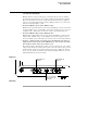
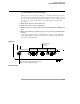
Markers make it easier to make precise measurements because the marker
measurement readouts show exact voltage and time positions for the markers.
The measurements are based on actual waveform data from the acquisition
system, not on approximations based on the display position, so you can be sure
that the values are highly accurate.
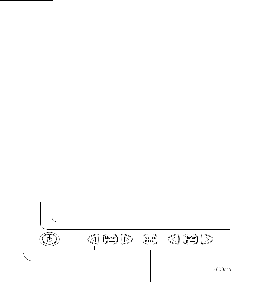
• To turn on Marker A, press the Marker A key.
Marker A has a solid line pattern on the waveform display. It is associated with
the first available source on the display. Press the key again to move to the next
available source. When there are no more sources, the marker turns off.
• To turn on Marker B, press the Marker B key.
Marker B has a dashed line pattern on the waveform display. It is associated
with the first available source on the display. Press the key again to move to
the next available source. When there are no more sources, the marker turns off.
• To move a marker on the waveform, press and hold the left arrow or
right arrow key next to the desired Marker key. Release the key when
the marker is at the desired waveform event.
The marker snaps to and follows the shape of the waveform on the screen. The
voltage value shown for a marker is the value of the waveform at the specified
horizontal time, which is set with the marker arrow keys. This is the default
mode. You can change the marker mode using the graphical interface. See the
built-in information system for details.
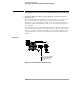
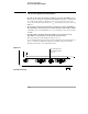
Figure 3-13
Marker Keys
Toggle Marker A
on and off
Toggle Marker B
on and off
Move each marker
with respect to the
waveform