
User`s guide


Setting Up Signals for a Stressed Eye Diagram Measurement Setting Up Generic and Advanced Signals
Agilent 81133A/81134A Pulse Generator User’s Guide, September 2008 59
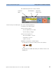
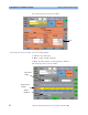
Connecting the Instruments
Connect the Pulse Generator, the Arbitrary Waveform Generator
and the DCA as follows:
CAUTION Before disconnecting/connecting any cables make sure that the
81134A output channels are turned off!
In detail:
1 Connect the 33250A output to the channel 2 delay control input
of the 81134A (use the BNC- SMA adaptor and a 20 dB
attenuator).
2 Connect a 20 dB attenuator each to the channel 1 and the
trigger input of the DCA.
3 Connect the 81134A channel 2 output to the DCA’s channel 1
input.
4 Connect the 81134A trigger output to the DCA’s trigger input.
5 Power on the three units after you have made all connections.
86100 DCA
Channel 1 Channel 2
Trigger In
Input
20 dB Attenuator
81134A Pulse Generator
Channel 2
Delay Control
Input
Channel 1
Output
TrigOut
33250A
Arbitrary Waveform Generator
BNC-SMA Adaptor and 20 dB Attenuator