
User`s guide
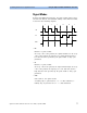


Combining Parameters for Signal Generation Using the Agilent 81133A/81134A Pulse Generator
Agilent 81133A/81134A Pulse Generator User’s Guide, September 2008 73
Clock Sources
The selected clock source defines the time base from which all other timing
parameters are derived. You can select between:
• Internal
The clock is derived from the internal YIG oscillator.
•External
Enables the external clock input (Clock In) to accept an external
clock signal that forms the time base. The frequency is measured
once by selecting the Measure function from the user interface
or as a remote SCPI command (
:MEASure:FREQuency?
).
This value is then used to calculate frequency- dependent values,
like the pulse width or the phase (available at the Channel
page).
For more information about the Measure function, please refer
to the Online Help.
• External 10 MHz Reference
Enables the external clock input (Clock In) to apply a 10 MHz
reference clock. This clock is used as a reference for all timing
parameters.
• Int. Direct/Ext. Direct
The direct modes allow changes of frequency without dropouts
in the range of 1:2. They are used for applications (precise clock
source) where dropouts would make a measurement impossible,
for example, PLL frequency sweeps and microprocessor clock
sweeps.
– Int. Direct
Allows you to vary the clock derived from the internal YIG
oscillator in the range of one octave.
Measure Function
Clock Source