
User`s guide


Using the Agilent 81133A/81134A Pulse Generator Timing of Generated Signals
78 Agilent 81133A/81134A Pulse Generator User’s Guide, September 2008
Pulses
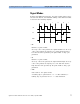
The following figure shows the typical timing for continuous pulses.
Characteristics • Pulse periods can be either generated continuously or can be
started manually or by the arming source.
• Delay, pulse width (or duty cycle) and deskew can be set for
each channel.
• The instrument mode is Pulse/Pattern.
• The pattern mode is Pulse.
• For the clock source, you can select from:
– Internal (YIG Oscillator)
– External signal at Clock Input
– External 10 MHz Reference at Clock Input
For more information about the clock sources, see “Clock
Sources” on page 73.
• The Trigger Out is generated with every clock pulse, but can be
optionally divided by any number in the range 1 ... 2
31
– 1.
See also “Trigger Out” on page 75.
Output
Channel 1
Output
Channel 2
Freq. Divider = 2
Duty Cycle
Delay
Trigger Out