
Technical data
112 16800 Series Portable Logic Analyzers Service Guide
5 Troubleshooting
7 Using an oscilloscope, verify the existence of logic- level
transitions by touching the oscilloscope probe to each
channel of Data Pod 1 and doing an Autoscale.
The signal levels that appear on the oscilloscope display
should correspond with the logic levels represented by the
10460- series pod being used.
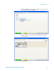
8 When you are done testing the pod channels, click Stop in
the Pattern Generator Setup dialog.
9 Repeat steps 1 through 8 for each of the remaining data
pods.
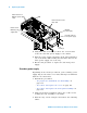
10 Connect one of the 10460- series clock pods to the end of
the pattern generator clock cable.
11 Using the oscilloscope, as in step 7, verify the existence of
logic- level transitions by touching the oscilloscope probe
to each clock output of the clock pod.
12 When you are done testing the pod channels, click Stop in
the Pattern Generator Setup dialog.
13 Click OK to close the Pattern Generator Setup dialog.