
Technical data

114 16800 Series Portable Logic Analyzers Service Guide
6 Replacing Assemblies
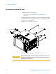
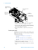
16800 Series Logic Analyzer Disassembly/Assembly
This chapter contains the instructions for removing and
replacing the assemblies of the logic analyzer. Also in this
chapter are instructions for returning assemblies.
Replacement Strategy
Some procedures in this section tell you to remove other
assemblies of the instrument, but do not give complete
instructions. In these cases, refer to the procedure for that
specific assembly for the instructions. The drawings here are
representative. Your parts may look different.
Tools Required
• T6, T10, T15, T25 TORX screwdrivers.
• #1 Pozi- drive screwdriver.
• 13/16 inch, deep- well nut driver.
• 5 mm nut driver.
• 1/4- inch hollow- shaft nut driver.
WARNING
Hazardous voltages exist on the power supply. To avoid electrical
shock, disconnect power from the instrument before performing
the following procedures. After disconnecting the power, wait at
least six minutes for the capacitors on the power supply board to
discharge before servicing the instrument.
CAUTION
Damage can occur to electronic components if you remove or
replace assemblies when the instrument is on or when the power
cable is connected. Never attempt to remove or install any assembly
with the instrument on or with the power cable connected.
CAUTION
Electrostatic discharge can damage electronic components. Use
grounded wrist straps and mats when performing any service to this
logic analyzer.