
Technical data
174 16800 Series Portable Logic Analyzers Service Guide
8 Theory of Operation
Fan Control The instrument uses a pair of 24 V fans driven
from a DC/DC boost converter circuit. This circuit creates a
linear voltage ramp from 12 V to 24 V across the operating
temperature range. The purpose of this circuit is to increase air
flow as needed while maintaining the lowest possible fan noise.
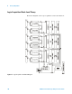
Front Panel Assembly
The identical front panel assembly with LCD is used on all
16800 Series logic analyzers. The front panel assembly is
composed of two PC boards comprising three independently
operating sub- systems. The two PC boards are the front panel
interface board and the keypad board. The three front panel
sub- systems are:
• Front panel keypad board.
• Front panel interface board.
• Front panel touch screen (Option 103).
Front Panel Keypad Board
The front panel switches consist of five buttons and one digital
encoder, the knob. When a button is pressed and released, or
the knob turned, a series of codes are sent back to the module
FPGA. When the module FPGA receives a front panel code, an
interrupt is sent to the system CPU. The resulting ISR will read
the code and act on it.
The module FPGA was used as a convenient place to put this
logic. This logic operates independently of the module
backplane logic also within the module FPGA.
Front Panel Interface Board
The front panel interface board plugs into the CPU
motherboard’s PCI Express x16 slot and provides a connection
point for flat- panel display communication.
The connectors J2 and J3 are connected to a Mitsubishi 15”
XGA
AA150XN01 TFT- LCD 1024x768 display:
• Connector J2 provides the data path back to an Adlink video
adapter.
• Connector J3 is used to provide the high- voltage needed to
light the display backlight. This high-voltage is generated
using a power inverter board, which is mounted on the front
panel interface board. This power inverter board is a TDK
CXA- 0384 DC-AC Inverter Unit.