
Technical data


Testing Performance 3
16800 Series Portable Logic Analyzers Service Guide 61
Determine and set eye finder Position (500 Mb/s mode)
1 On the 8133A pulse generator, in the PULSE setup for
CHANNEL 2, press the COMP button to return the
outputs to normal.
2 Change the oscilloscope’s horizontal position to 725 ps (or
as required) to center the measured pulse on the
oscilloscope display.
3 Verify the DC offset and adjust it if necessary. See
page 41.
4 Verify the oscilloscope Deskew and adjust if necessary.
See page 42.
5 Adjust the measured pulse width from the pulse generator
to 1.5 ns (minus the test margin) as described on
page 43.
Do not change the pulse generator frequency yet.
6 Select the Sampling tab.
7 Click Thresholds and Sample Positions.... A dialog appears
telling you that acquired data will be erased. Select the
Yes button, erasing acquired data.
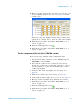
8 In the Thresholds and Sample Positions dialog, expand
“My Bus 1”.
9 If the blue bars are not vertically aligned, align them. See
page 49.
10 Grab the blue bar for “My Bus 1” and move it to
approximately 600 ps. All blue bars will follow.
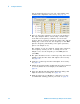
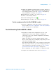
11 Run eye finder and note the average sampling position
chosen by eye finder:______ps. In the following example,
the average sampling position is 600 ps. Note that in this
step, you place the blue bars in the narrow window (not
the wide window) that appears just to the right of zero in
the eye finder display. Then run eye finder. The position