Agilent 81689A, 81689B and 81649A Compact Tunable Laser Modules User’s Guide S1
Notices This document contains proprietary information that is protected by copyright. All rights are reserved. No part of this document may reproduced in (including electronic storage and retrieval or translation into a foreign language) without prior agreement and written consent from Agilent Technologies Deutschland GmbH as governed by United States and international copywright laws. Copyright 2001 by: Agilent Technologies Deutschland GmbH Herrenberger Str.
Safety Summary Safety Summary The following general safety precautions must be observed during all phases of operation, service, and repair of this instrument. Failure to comply with these precautions or with specific warnings elsewhere in this manual violates safety standards of design, manufacture, and intended use of the instrument. Agilent Technologies Inc. assumes no liability for the customer’s failure to comply with these requirements.
Safety Summary WARNING You MUST return instruments with malfunctioning laser modules to an Agilent Technologies Sales/Service Center for repair and calibration. Line Power Requirements The Agilent 81689A, Agilent 81689B and Agilent 81649A Compact Tunable Laser Modules operate when installed in the Agilent 8163A and B Lightwave Multimeters, the Agilent 8164A and B Lightwave Measurement Systems, or the Agilent 8166A and B Lightwave Multichannel Systems.
Safety Summary Initial Safety Information for Tunable Laser Modules The laser sources specified by this user guide are classified according to IEC 60825-1 (2001) The laser sources comply with 21 CFR 1040.10 except for deviations pursuant to Laser Notice No.
Safety Summary Laser Safety Labels Laser class 1M label Figure 1 Class 1M Safety Label - Agilent 81649A/89A/89B A sheet of laser safety labels is included with the laser module as required. In order to meet the requirements of IEC 60825-1 we recommend that you stick the laser safety labels, in your language, onto a suitable location on the outside of the instrument where they are clearly visible to anyone using the instrument.
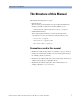
The Structure of this Manual The Structure of this Manual This manual is divided into two parts: • Getting Started This section gives an introduction to the Compact Tunable Laser modules. and aims to make these modules familiar to you: – “Getting Started with Tunable Laser Sources” on page 17.
The Structure of this Manual 8 Agilent 81689A, 81689B and 81649A Tunable Laser Modules User’s Guide, Third Edition
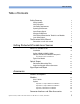
Table of Contents Table of Contents Safety Summary Safety Symbols Initial Inspection Line Power Requirements Operating Environment Input/Output Signals Storage and Shipment Initial Safety Information for Tunable Laser Modules Laser Safety Labels The Structure of this Manual 3 3 3 4 4 4 4 5 6 8 Conventions used in this manual 8 Getting Started with Tunable Laser Sources 17 What is a Tunable Laser? Installation Agilent 81689A, 81689B, 81649A Compact Tunable Laser Module Front panels Front Panel Contro
Table of Contents Options 021, 071: Straight Contact Connectors Options 022, 072: Angled Contact Connectors Specifications 31 33 Definition of Terms Absolute Wavelength Accuracy Linewidth Minimum Output Power Modulation Extinction Ratio Modulation Frequency Range Output Power Output Isolation Peak Power Polarization Extinction Ratio Power Flatness Over Modulation Power Flatness Versus Wavelength Power Linearity Power Repeatability Power Stability Relative Intensity Noise (RIN) Relative Wavelength Accura
Table of Contents Instrument Specification 48 Performance Test Instructions 48 General Test Setup Wavelength Tests General Settings of Wavelength Meters for all Wavelength Tests Wavelength Accuracy Relative Wavelength Accuracy Absolute Wavelength Accuracy Wavelength Repeatability Power Tests Maximum Output Power Power Linearity Power Linearity - High Power Test Example (Agilent 81689B) Power Linearity Power Flatness over Wavelength Power Flatness over Wavelength Power Stability Optional Tests Sig
Table of Contents Signal-to-Source Spontaneous Emission (BW = 1 nm) Agilent 81649A Performance Test Test Equipment Used Relative Wavelength Accuracy Wavelength Repeatability Maximum Power Test Power Linearity Power Flatness Power Stability Optional Test Signal-to-Source Spontaneous Emission (BW = 1 nm) Cleaning Information 79 81 82 83 84 85 86 87 87 88 88 89 Safety Precautions Why is it important to clean optical devices? What do I need for proper cleaning? Standard Cleaning Equipment Dust and shutter
Table of Contents 102 How to clean instruments with an optical glass plate 103 How to clean instruments with a physical contact interface 103 How to clean instruments with a recessed lens interface 104 How to clean optical devices which are sensitive to mechanical stress and pressure How to clean metal filters or attenuator gratings Additional Cleaning Information How to clean bare fiber ends How to clean large area lenses and mirrors Other Cleaning Hints Agilent 81689A, 81689B and 81649A Tunable Lase
Table of Contents 14 Agilent 81689A, 81689B and 81649A Tunable Laser Modules User’s Guide, Third Edition
List of Figures List of Figures Figure 1 Class 1 Safety Label - Agilent 81650A/51A/52A/54A/11A/12A/13A/14A Figure 2 Class 1M Safety Label - Agilent 81655A/6A/7A, 81662A/3A/81480B/82B/ 81640B/42B/80B/82B/72B/49A/89A/89B6 Figure 3 Agilent 81689A Compact Tunable Laser Module . . . . . . . Figure 4 Agilent 81689B Compact Tunable Laser Module . . . . . . . Figure 5 Agilent 81649A Compact Tunable Laser Module . . . . . . . Figure 6 PMF Output Connector . . . . . . . . . . . . .
List of Figures 16 Agilent 81689A, 81689B and 81649A Tunable Laser Modules User’s Guide, Third Edition
Getting Started with Tunable Laser Sources Agilent 81689A, 81689B and 81649A Tunable Laser Modules User’s Guide, Third Edition 17
Getting Started with Tunable Laser Sources This chapter describes the Agilent 81689A, Agilent 81689B and Agilent 81649A Compact Tunable Laser modules.
What is a Tunable Laser? Getting Started with Tunable Laser Sources What is a Tunable Laser? A Tunable Laser is a laser source for which the wavelength can be varied through a specified range. The Agilent Technologies range of tunable laser modules also allow you to set the output power, and to choose between continuous wave or modulated power.
Getting Started with Tunable Laser Sources What is a Tunable Laser? Agilent 81689B with Agilent 81689B with Straight Contact Connector Angled Contact Connector Figure 4 Agilent 81689B Compact Tunable Laser Module Agilent 81649A with Agilent 81649A with Straight Contact Connector Angled Contact Connector Figure 5 Agilent 81649A Compact Tunable Laser Module Front Panel Controls and Indicators Switch the laser source on or off using the switch on its front panel, using the [State] parameter in the instru
What is a Tunable Laser? Getting Started with Tunable Laser Sources Typical Use Models Brief description The Agilent 81689A Compact Tunable Laser module operates in the C-band between 1525 nm and 1575 nm. The Agilent 81689B Compact Tunable Laser module also operates in the C-band between 1525 nm and 1575 nm. When compared with the Agilent 8169A, the Agilent 8169B offers increased output power, and higher relative wavelength accuracy and wavelength stability.
Getting Started with Tunable Laser Sources Optical Output Optical Output Polarization Maintaining Fiber A Polarization maintaining fiber (PMF) output is available as an option for Agilent 81689A, Agilent 81689B and Agilent 81649A Compact Tunable Laser modules. PMF is aligned to maintain the state of polarization. A well defined state of polarization helps ensure constant measurement conditions. The fiber is of Panda type, with TE mode in the slow axis in line with the connector key..
Signal Input and Output Getting Started with Tunable Laser Sources CA U TI O N If the contact connector on your instrument is angled, you can only use cables with angled connectors with the instrument. Angled Contact Connector Symbol Figure 7 Straight Contact Connector Symbol Angled and Straight Contact Connector Symbols Figure 7 shows the symbols that tell you whether the contact connector of your Tunable Laser module is angled or straight. The angled contact connector symbol is colored green.
Getting Started with Tunable Laser Sources 24 Signal Input and Output Agilent 81689A, 81689B and 81649A Tunable Laser Modules User’s Guide, Third Edition
Accessories Agilent 81689A, 81689B and 81649A Tunable Laser Modules User’s Guide, Third Edition 25
Accessories The Agilent 81689A, Agilent 81689B and Agilent 81649A Compact Tunable Laser modules are available in various configurations for the best possible match to the most common applications. This chapter provides information on the available options and accessories.
Modules and Options Accessories Modules and Options Figure 8 shows all the options that are available for Agilent 81689A, Agilent 81689B and Agilent 81649A Compact Tunable Laser modules, and the instruments that support these modules.
Accessories Modules Modules Agilent 81689A, Agilent 81689B and Agilent 81649A Compact Tunable Laser modules can be hosted by: • Agilent 8163A and Agilent 8163B Lightwave Multimeters, • Agilent 8164A and Agilent 8164B Lightwave Measurement Systems, • Agilent 8166A and Agilent 8166B Lightwave Multichannel Systems. Compact Tunable Laser Modules Model No.
Modules Accessories Options Option 021 - Compact Tunable Laser Modules Standard single-mode fiber, for straight contact connectors. Option 022 - Compact Tunable Laser Modules Standard single-mode fiber, for angled contact connectors. Option 071 - All Tunable Laser Modules Polarization-maintaining fiber, Panda-type, for straight contact connectors. Option 072 - All Tunable Laser Modules Polarization-maintaining fiber, Panda-type, for angled contact connectors.
Accessories Connector Interfaces and Other Accessories Connector Interfaces and Other Accessories Options 021, 071: Straight Contact Connectors If you want to use straight connectors (such as FC/PC, Diamond HMS10, DIN, Biconic, SC, ST or D4) to connect to the instrument, you must do the following: 1 Attach your connector interface to the interface adapter. See Table 2 for a list of the available connector interfaces. 2 Connect your cable (see Figure 9).
Connector Interfaces and Other Accessories Accessories Options 022, 072: Angled Contact Connectors If you want to use angled connectors (such as FC/APC, Diamond HRL10, or SC/APC) to connect to the instrument, you must do the following: 1 Attach your connector interface to the interface adapter. See Table 3 for a list of the available connector interfaces. 2 Connect your cable (see Figure 10).
Accessories 32 Connector Interfaces and Other Accessories Agilent 81689A, 81689B and 81649A Tunable Laser Modules User’s Guide, Third Edition
Specifications Agilent 81689A, 81689B and 81649A Tunable Laser Modules User’s Guide, Third Edition 33
Specifications The Agilent 81689A, Agilent 81689B and Agilent 81649A Compact Tunable Laser modules are produced to the ISO 9001 international quality system standard as part of Agilent Technologies’ commitment to continually increasing customer satisfaction through improved quality control. Specifications describe the modules’ warranted performance. Supplementary performance characteristics describe the modules non-warranted typical performance.
Definition of Terms Specifications Definition of Terms This section defines terms that are used both in this chapter and “Performance Tests” on page 45. Generally, all specifications apply for the given environmental conditions and after warmup time. Measurement principles are indicated. Alternative measurement principles of equal value are also acceptable. Absolute Wavelength Accuracy The maximum difference between the actual wavelength and the displayed wavelength of the TLS.
Specifications Definition of Terms Modulation Extinction Ratio The ratio of total power in on-state to total power in off-state, expressed in dB. Conditions: Internal or external modulation, tunable laser at highest power setting. Measurement with optical spectrum analyzer. Tunable laser switched on and off. Modulation Frequency Range The range of frequencies for which the modulation index is above − 3 dB of the highest modulation index.
Definition of Terms Specifications Measurement with a polarization analyzer at the end of a polarizationmaintaining patchcord, by sweeping the wavelength, thereby creating circular traces on the Poincaré sphere, then calculating the polarization extinction ratio from the circle diameters.
Specifications Definition of Terms Conditions: uninterrupted TLS output power, constant wavelength, temperature within ±1 K, short time span. Measurement with optical power meter. N O TE The long-term power repeatability can be obtained by taken the power repeatability and power stability into account. Power Stability The change of the power level during given time span, expressed as ± half the span (in dB) between the highest and lowest actual power.
Definition of Terms Specifications Return Loss The ratio of optical power incident to the TLS output port, at the TLS's own wavelength, to the power reflected from the TLS output port. Conditions: TLS disabled. Sidemode Suppression Ratio The ratio of average signal power to the optical power of the highest sidemode within a distance from 0.1 to 6 GHz to the signal's optical frequency, expressed in dB.
Specifications Definition of Terms Wavelength Repeatability The random uncertainty in reproducing a wavelength after detuning and re-setting the wavelength. The wavelength repeatability is ± half the span between the maximum and the minimum value of all actual values of this wavelengths. Conditions: uninterrupted TLS output power, constant power level, temperature within operating temperature range, coherence control off, short time span. Measurement with wavelength meter at high power output.
Tunable Laser Module Specifications Specifications Tunable Laser Module Specifications Wavelength range Wavelength resolution Agilent 81689A Agilent 81689B Agilent 81649A 1525 nm to 1575 nm 1525 nm to 1575 nm 1570 nm to 1620 nm 0.01 nm, 1.25 GHz at 1550 nm 0.01 nm, 1.25 GHz at 1550 nm 0.01 nm, 1.17 GHz at 1595 nm Absolute wavelength accuracy (typ.)1 ± 0.3 nm ± 0.3 nm ± 0.3 nm Relative wavelength accuracy 1 ± 0.3 nm ± 0.15 nm ± 0.15 nm Wavelength repeatability 1 ± 0.05 nm ± 0.05 nm ± 0.
Specifications Relative Intensity noise (RIN, typ.) Dimensions Supplementary Performance Characteristics Agilent 81689A Agilent 81689B Agilent 81649A < −137 dB/Hz (100 MHz - 2.5 GHz) at + 3 dBm < −137 dB/Hz (100 MHz - 2.5 GHz) at + 7 dBm < −137 dB/Hz (100 MHz - 2.5 GHz) at + 3 dBm 75 mm H, 32 mm W, 335 mm D 75 mm H, 32 mm W, 335 mm D 75 mm H, 32 mm W, 335 mm D (2.8” × 1.3” × 13.2”) (2.8” × 1.3” × 13.2”) (2.8” × 1.3” × 13.2”) 1 kg Weight 1 kg 1 kg 1. At CW operation.
Supplementary Performance Characteristics Specifications General Output Isolation (typ.) Return loss (typ.) Polarization Maintaining Fiber (Options 071, 072): Recommended Recalibration Period: Warm-up Time: 38 dB 55 dB (options 022, 072); 40 dB (options 021, 071). Fiber type: Panda. Orientation: TE mode in slow axis, in line with connector key. Extinction Ratio: 16 dB typ. 2 years. < 40 min, immediate operation after boot-up.
Specifications 44 Supplementary Performance Characteristics Agilent 81689A, 81689B and 81649A Tunable Laser Modules User’s Guide, Third Edition
Performance Tests Agilent 81689A, 81689B and 81649A Tunable Laser Modules User’s Guide, Third Edition 45
Performance Tests The procedures in this section tests the optical performance of the instrument. The complete specifications to which the Agilent 81689A, Agilent 81689B and Agilent 81649A Compact Tunable Laser modules are tested are given in “Specifications” on page 33. All tests can be performed without access to the interior of the instrument. The performance tests refer specifically to tests using the Diamond HMS10/Agilent connector.
Required Test Equipment Performance Tests Required Test Equipment The equipment required for the Performance Test is listed in Table 4. Any equipment that satisfies the critical specifications of the equipment given in Table 4 may be substituted for the recommended models.
Performance Tests Performance Test Instructions Test Failure Always ensure that you use the correct cables and adapters, and that all connectors are undamaged and extremely clean. If the Agilent 81689A, Agilent 81689B or Agilent 81649A Compact Tunable Laser Modules fails any performance test, return the instrument to the nearest Agilent Technologies Sales/Service Office for repair. Instrument Specification Specifications are the performance characteristics of the instrument which are certified.
Performance Test Instructions Performance Tests General Test Setup Insert an Agilent 81689A, Agilent 81689B or Agilent 81649A Compact Tunable Laser Module from the front into slot 1 of the Agilent 8164A/B Lightwave Measurement System. Wavelength Tests Connect the Tunable Laser module to the Wavelength Meter as shown in Figure 11.
Performance Tests Performance Test Instructions 2 Set the menu parameters to the values shown in Table 5. Table 5 Tunable Laser Channel Settings Tunable Laser Channel Menu Parameters Values <λ> 3 Set the wavelength and power of your Tunable Laser module to the values given in Table 6.
Performance Test Instructions Performance Tests NOTE The largest Maximum Deviation is the largest positive value and the smallest Minimum Deviation is the largest negative value (largest deviation above and below zero respectively). 11 Determine the Relative Wavelength Accuracy Result: Subtract the Smallest Minimum Deviation from the Largest Maximum Deviation. Record this value as the Relative Wavelength Accuracy Result.
Performance Tests Performance Test Instructions 8 Measure the wavelength with the Wavelength Meter and note the result in test record. 9 Repeat steps 6 through 8 with all wavelength settings given by “from {wavelength} to REF” in the test record. 10 From all wavelength measurements pick the largest measured value and the smallest measured value. 11 Calculate the wavelength repeatability by subtracting the largest measured value from the smallest measured value.
Performance Test Instructions Performance Tests 3 Move to the Tunable Laser channel of the Agilent 8164A/B Lightwave Measurement System and press [Menu]. 4 Set the menu parameters to the values shown in Table 5. 5 Set the wavelength and power for each Tunable Laser module to the values given in Table 9. Table 9 Reference Wavelength and Power Values for Maximum Output Power Tests Wavelength [λ] Power [P] Agilent 81689A 1525.000 nm +13.00 dBm Agilent 81689B 1525.000 nm +13.
Performance Tests Performance Test Instructions Power Linearity Power Linearity - High Power Test 1 Set up the equipment as shown in Figure 12. 2 Move to the Tunable Laser channel of the Agilent 8164A/B Lightwave Measurement System and press [Menu]. 3 Set the menu parameters to the values shown in Table 5.
Performance Test Instructions Performance Tests 13 Note the maximum and minimum values of the calculated Power Linearity values for the various settings and record these in the test record. 14 Subtract the minimum values from the maximum values of the Power Linearity for the various settings. Record these as the Total Power Linearity.
Performance Tests Performance Test Instructions Power Flatness over Wavelength Power Flatness over Wavelength 1 Set up the equipment as shown in Figure 12 2 Move to the Tunable Laser channel of the Agilent 8164A/B Lightwave Measurement System and press [Menu]. 3 Set the menu parameters to the values shown in Table 5. 4 Set the wavelength and power for each Tunable Laser module to the values given in Table 11.
Performance Test Instructions Performance Tests 12 Set wavelength and power as given in Table 12.. Table 12 Wavelength and Power Settings for Power Flatness over Wavelength at minimum output power Wavelength [λ] Power [P] Agilent 81689A 1525.000 nm - 3.000 dBm Agilent 81689B 1525.000 nm +0.000 dBm Agilent 81649A 1570.000 nm - 3.000 dBm Module 13 Set the power meter channel of the 81626B to the following settings: a Select Automatic ranging. This is the default setting.
Performance Tests Performance Test Instructions Power Stability Follow the steps below to measure the power stability: 1 Set up the equipment as shown in Figure 12. 2 Move to the Tunable Laser channel of the Agilent 8164A/B Lightwave Measurement System and press [Menu]. 3 Set the menu parameters to the values shown in Table 5. 4 Set the wavelength and power for each Tunable Laser module to the values given in Table 13.
Optional Tests Performance Tests • the “∆P” value in the Power Stability field of the test record. NOTE It is sufficient to test Power Stability for approximately 15 minutes, rather than 1 hour, since this ensures that the power control loop works correctly. Optional Tests Signal-to-Source Spontaneous Emission See “Specifications” on page 33 for a definition of Signal-to-Source Spontaneous Emission.
Performance Tests Optional Tests 5 Set the wavelenght of your Tunable Laser module to the value given in Table 14. Table 14 Wavelength Settings for Source Spontaneous Emmission Tests Wavelength [λ] Module Agilent 81689A 1525.000 nm Agilent 81689B 1525.000 nm Agilent 81649A 1570.000 nm 6 Set the power for each Tunable Laser module to the maximum specified output power given in the Test Record. 7 Press the key beside the laser output to switch on the laser. 8 Initialize the Optical Specrum Analyzer.
Optional Tests Performance Tests Figure 14 Signal-to-Spectral SSE Measurement 13 To reflect for a specified value at 1 nm bandwidth related to the measurement bandwidth of 0.5 nm, reduce the measured absolute value by 3 dB and note the result in the test record. For example: measured value at RES BW = 0.05 nm BW - 44.5 dB absolute of measured value at RES BW = 0.05 nm BW 44.5 dB correction to a RES BW = 1 nm 44.5 dB - 3 dB = 41.5 dB Result noted in Test Record 41.
Performance Tests 62 Optional Tests Agilent 81689A, 81689B and 81649A Tunable Laser Modules User’s Guide, Third Edition
Test Record Performance Tests Test Record Agilent 81689A, 81689B and 81649A Tunable Laser Modules User’s Guide, Third Edition 63
Performance Tests 64 Test Record Agilent 81689A, 81689B and 81649A Tunable Laser Modules User’s Guide, Third Edition
Test Record Performance Tests Test Record Agilent 81689A Performance Test Page 1 of 7 Test Facility: ________________________________ Report No. _________________ ________________________________ Date _________________ ________________________________ Customer _________________ ________________________________ Tested By _________________ Model Agilent 81689A Tunable Laser Module 1550 nm Serial No.
Performance Tests Test Record Agilent 81689A Performance Test Page 2 of 7 Report No. ________ Date_______ Model Agilent 81689A Tunable Laser Test Equipment Used Description Trace No. Cal. Due Date 1. Lightwave Measurement System 8164A/B _________ ____n/a___ 2. Lightwave Multimeter 8163A/B _________ ____n/a___ 3. Optical Head Interface Module Optical Head Interface Module 81618A 81619A _________ _________ ____n/a___ ____n/a___ 4.
Test Record Performance Tests Agilent 81689A Performance Test Model Agilent 81689A Tunable Laser Page 3 of 7 Report No. ________ Date_______ Relative Wavelength Accuracy Repetition 1 Wavelength Setting Repetition 2 Wavelength Measured Wavelength Deviation 1 Repetition 3 Wavelength Measured Wavelength Deviation 1 Wavelength Measured Wavelength Deviation 1 1525.000 nm nm nm nm nm nm nm 1535.000 nm nm nm nm nm nm nm 1545.000 nm nm nm nm nm nm nm 1555.
Performance Tests Test Record Agilent 81689A Performance Test Model Agilent 81689A Tunable Laser Absolute Wavelength Accuracy Result Page 4 of 7 Report No. ________ Date_______ Largest Value of Deviation (= largest value of either Largest Maximum Deviation or Smallest Minimum Deviation) Absolute Wavelength Accuracy ______nm Test Limit: 1.0 nm Specification: 0.6 nm typical Measurement Uncertainty: ± 0.6 pm Wavelength Repeatability Repeatability of 1525.
Test Record Performance Tests Agilent 81689A Performance Test Page 5 of 7 Report No. ________ Date_______ Model Agilent 81689A Tunable Laser Maximum Power Test Wavelength Setting Power Measured Minimum Specification 1525.000 nm dBm + 6.00 dBm 1535.000 nm dBm + 6.00 dBm 1540.000 nm dBm + 6.00 dBm 1550.000 nm dBm + 6.00 dBm 1560.000 nm dBm + 6.00 dBm 1570.000 nm dBm + 6.00 dBm 1575.000 nm dBm + 6.00 dBm Measurement Uncertainty: ± 0.
Performance Tests Test Record Agilent 81689A Performance Test Model Agilent 81689A Tunable Laser Page 6 of 7 Report No. ________ Date_______ Power Flatness Wavelength Start = REF Flatness = 1525 nm Power Deviation at P = + 6.0 dBm Power Deviation at P = - 3.0 dBm 0.00 dB 0.00 dB 1530 nm dB dB 1540 nm dB dB 1550 nm dB dB 1560 nm dB dB 1570 nm dB dB 1575 nm dB dB Maximum deviation dB dB Minimum deviation dB dB Maximum − Minimum Deviation dB dB Specification 0.60 dBpp 0.
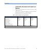
Test Record Performance Tests Agilent 81689A Performance Test Model Agilent 81689A Tunable Laser Page 7 of 7 Report No. ________ Date_______ Optional Test Signal-to-Source Spontaneous Emission (BW = 1 nm) Minimum Test Limit Typical dB 30 dB 39 dB + 6.00 dBm dB 30 dB 39 dB 1545 nm + 6.00 dBm dB 30 dB 39 dB 1555 nm + 6.00 dBm dB 30 dB 39 dB 1565 nm + 6.00 dBm dB 30 dB 39 dB 1575 nm +6.00 dBm dB 30 dB 39 dB Wavelength Output Power 1525 nm + 6.
Performance Tests 72 Test Record Agilent 81689A, 81689B and 81649A Tunable Laser Modules User’s Guide, Third Edition
Test Record Performance Tests Test Record Agilent 81689B Performance Test Page 1 of 7 Test Facility: ________________________________ Report No. _________________ ________________________________ Date _________________ ________________________________ Customer _________________ ________________________________ Tested By _________________ Model Agilent 81689B Tunable Laser Module 1550 nm Serial No.
Performance Tests Test Record Agilent 81689B Performance Test Page 2 of 7 Report No. ________ Date_______ Model Agilent 81689B Tunable Laser Test Equipment Used Description Trace No. Cal. Due Date 1. Lightwave Measurement System 8164A/B _________ ____n/a___ 2. Lightwave Multimeter 8163A/B _________ ____n/a___ 3. Optical Head Interface Module Optical Head Interface Module 81618A 81619A _________ _________ ____n/a___ ____n/a___ 4.
Test Record Performance Tests Agilent 81689B Performance Test Model Agilent 81689B Tunable Laser Page 3 of 7 Report No. ________ Date_______ Relative Wavelength Accuracy Repetition 1 Wavelength Setting Repetition 2 Wavelength Measured Wavelength Deviation 1 Repetition 3 Wavelength Measured Wavelength Deviation 1 Wavelength Measured Wavelength Deviation 1 1525.000 nm nm nm nm nm nm nm 1535.000 nm nm nm nm nm nm nm 1545.000 nm nm nm nm nm nm nm 1555.
Performance Tests Test Record Agilent 81689B Performance Test Model Agilent 81689B Tunable Laser Absolute Wavelength Accuracy Result Page 4 of 7 Report No. ________ Date_______ Largest Value of Deviation (= largest value of either Largest Maximum Deviation or Smallest Minimum Deviation) Absolute Wavelength Accuracy _______nm Test Limit: 1.0 nm Specification: 0.6 nm typical Measurement Uncertainty: ± 0.6 pm Wavelength Repeatability Repeatability of 1525.
Test Record Performance Tests Agilent 81689B Performance Test Page 5 of 7 Report No. ________ Date_______ Model Agilent 81689B Tunable Laser Maximum Power Test Wavelength Setting Power Measured Minimum Specification 1525.000 nm dBm + 10.00 dBm 1535.000 nm dBm + 10.00 dBm 1540.000 nm dBm + 10.00 dBm 1550.000 nm dBm + 10.00 dBm 1560.000 nm dBm + 10.00 dBm 1570.000 nm dBm + 10.00 dBm 1575.000 nm dBm + 10.00 dBm Measurement Uncertainty: ± 0.
Performance Tests Test Record Agilent 8168B Performance Test Model Agilent 81689B Tunable Laser Page 6 of 7 Report No. ________ Date_______ Power Flatness Wavelength Start = REF Flatness = 1525 nm Power Deviation at P = + 10.0 dBm Power Deviation at P = - 3.0 dBm 0.00 dB 0.00 dB 1530 nm dB dB 1540 nm dB dB 1550 nm dB dB 1560 nm dB dB 1570 nm dB dB 1575 nm dB dB Maximum deviation dB dB Minimum deviation dB dB Maximum − Minimum Deviation dB dB Specification 0.40 dBpp 0.
Test Record Performance Tests Agilent 81689B Performance Test Model Agilent 81689B Tunable Laser Page 7 of 7 Report No. ________ Date_______ Optional Test Signal-to-Source Spontaneous Emission (BW = 1 nm) Minimum Test Limit Typical dB 40 dB 44 dB + 10.00 dBm dB 40 dB 44 dB 1545 nm + 10.00 dBm dB 40 dB 44 dB 1555 nm + 10.00 dBm dB 40 dB 44 dB 1565 nm + 10.00 dBm dB 40 dB 44 dB 1575 nm + 10.00 dBm dB 40 dB 44 dB Wavelength Output Power 1525 nm + 10.
Performance Tests 80 Test Record Agilent 81689A, 81689B and 81649A Tunable Laser Modules User’s Guide, Third Edition
Test Record Performance Tests Test Record Agilent 81649A Performance Test Page 1 of 8 Test Facility: ________________________________ Report No. _________________ ________________________________ Date _________________ ________________________________ Customer _________________ ________________________________ Tested By _________________ Model Agilent 81649A Tunable Laser Module 1595 nm Serial No.
Performance Tests Test Record Agilent 81649A Performance Test Page 2 of 8 Report No. ________ Date_______ Model Agilent 81649A Tunable Laser Test Equipment Used Description Trace No. Cal. Due Date 1. Lightwave Measurement System 8164A/B _________ ____n/a___ 2. Lightwave Multimeter 8163A/B _________ ____n/a___ 3. Optical Head Interface Module Optical Head Interface Module 81618A 81619A _________ _________ ____n/a___ ____n/a___ 4.
Test Record Performance Tests Agilent 81649A Performance Test Model Agilent 81649A Tunable Laser Page 3 of 8 Report No. ________ Date_______ Relative Wavelength Accuracy Repetition 1 Repetition 2 Repetition 3 Wavelength Setting Wavelength Measured Wavelength Deviation 1 Wavelength Measured Wavelength Deviation 1 Wavelength Measured Wavelength Deviation 1 1570.000 nm nm nm nm nm nm nm 1575.000 nm nm nm nm nm nm nm 1580.000 nm nm nm nm nm nm nm 1585.
Performance Tests Test Record Agilent 81649A Performance Test Model Agilent 81649A Tunable Laser Page 4 of 8 Report No. ________ Date_______ Relative Wavelength Accuracy Largest Maximum Deviation ________nm Summary of All Repetitions Smallest Minimum Deviation _______nm Relative Wavelength Accuracy Result (= Largest Maximum Deviation − Smallest Minimum Deviation) Relative Wavelength Accuracy _______nm Specification: Measurement Uncertainty: Absolute Wavelength Accuracy Result 0.3 nm ± 0.
Test Record Performance Tests Agilent 81689A Performance Test Page 5 of 8 Report No. ________ Date_______ Model Agilent 81689A Tunable Laser Repeatability of 1620.000 nm (= reference) Initial Setting Measurement Result REF = nm from 1570000 nm to REF nm from 1580.000 nm to REF nm from 1590.000 nm to REF nm from 1600.000 nm to REF nm from 1610.
Performance Tests Test Record Agilent 81649A Performance Test Page 6 of 8 Report No. ________ Date_______ Model Agilent 81649A Tunable Laser Power Linearity Power Setting from start Start = REF + 6.00 dBm Measured Relative Power from start 0.00 dB Power reduction from start + 0.00 dB = + 5.00 dBm dB + 1.00 dB = dB + 4.00 dBm dB + 2.00 dB = dB + 3.00 dBm dB + 3.00 dB = dB + 2.00 dBm dB + 4.00 dB = dB + 1.00 dBm dB + 5.00 dB = dB − 0.0 dBm dB + 6.00 dB = dB − 1.
Test Record Performance Tests Agilent 81689A Performance Test Model Agilent 81689A Tunable Laser Page 7 of 8 Report No. ________ Date_______ Power Flatness Wavelength Start = REF Flatness = 1570 nm Power Deviation at P = + 6.0 dBm Power Deviation at P = - 3.0 dBm 0.00 dB 0.
Performance Tests Test Record Agilent 81649A Performance Test Model Agilent 81649A Tunable Laser Page 8 of 8 Report No. ________ Date_______ Optional Test Signal-to-Source Spontaneous Emission (BW = 1 nm) Minimum Test Limit Typical dB 37 dB 42 dB + 6.00 dBm dB 37 dB 42 dB 1545 nm + 6.00 dBm dB 37 dB 42 dB 1555 nm + 6.00 dBm dB 37 dB 42 dB 1565 nm + 6.00 dBm dB 37 dB 42 dB 1575 nm +6.00 dBm dB 37 dB 42 dB Wavelength Output Power 1525 nm + 6.
Cleaning Information Agilent 81689A, 81689B and 81649A Tunable Laser Modules User’s Guide, Third Edition 89
Cleaning Information The following Cleaning Information contains some general safety precautions, which must be observed during all phases of cleaning. Consult your specific optical device manuals or guides for full information on safety matters. Please try, whenever possible, to use physically contacting connectors, and dry connections. Clean the connectors, interfaces, and bushings carefully after use.
Safety Precautions Cleaning Information Safety Precautions Please follow the following safety rules: • Do not remove instrument covers when operating. • Ensure that the instrument is switched off throughout the cleaning procedures. • Use of controls or adjustments or performance of procedures other than those specified may result in hazardous radiation exposure. • Make sure that you disable all sources when you are cleaning any optical interfaces.
Cleaning Information What do I need for proper cleaning? Furthermore, the power density may burn dust into the fiber and cause additional damage (for example, 0 dBm optical power in a single mode fiber causes a power density of approximately 16 million W/m2). If this happens, measurements become inaccurate and non-repeatable. Cleaning is, therefore, an essential yet difficult task.
What do I need for proper cleaning? Cleaning Information We suggest these protective coverings should be kept on the equipment at all times, except when your optical device is in use. Be careful when replacing dust caps after use. Do not press the bottom of the cap onto the fiber too hard, as any dust in the cap can scratch or pollute your fiber surface. If you need further dust caps, please contact your nearest Agilent Technologies sales office.
Cleaning Information What do I need for proper cleaning? Soft tissues These are available from most stores and distributors of medical and hygiene products such as supermarkets or chemists' shops. We recommend that you do not use normal cotton tissues, but multilayered soft tissues made from non-recycled cellulose. Cellulose tissues are very absorbent and softer. Consequently, they will not scratch the surface of your device over time.
What do I need for proper cleaning? Cleaning Information When spraying compressed air, hold the can upright. If the can is held at a slant, propellant could escape and dirty your optical device. First spray into the air, as the initial stream of compressed air could contain some condensation or propellant. Such condensation leaves behind a filmy deposit. Please be friendly to your environment and use a CFC-free aerosol.
Cleaning Information What do I need for proper cleaning? Only use isopropyl alcohol in your ultrasonic bath, as other solvents may cause damage. Warm water and liquid soap Only use water if you are sure that there is no other way of cleaning your optical device without causing corrosion or damage. Do not use hot water, as this may cause mechanical stress, which can damage your optical device. Ensure that your liquid soap has no abrasive properties or perfume in it.
Preserving Connectors Cleaning Information Preserving Connectors Listed below are some hints on how best to keep your connectors in the best possible condition. Making Connections Before you make any connection you must ensure that all cables and connectors are clean. If they are dirty, use the appropriate cleaning procedure. When inserting the ferrule of a patchcord into a connector or an adapter, make sure that the fiber end does not touch the outside of the mating connector or adapter.
Cleaning Information Which Cleaning Procedure should I use ? Which Cleaning Procedure should I use ? Light dirt If you just want to clean away light dirt, observe the following procedure for all devices: • Use compressed air to blow away large particles. • Clean the device with a dry cotton swab. • Use compressed air to blow away any remaining filament left by the swab. Heavy dirt If the above procedure is not enough to clean your instrument, follow one of the procedures below.
How to clean connector adapters Cleaning Information To assess the projection of the emitted light beam you can use an infrared sensor card. Hold the card approximately 5 cm from the output of the connector. The invisible emitted light is projected onto the card and becomes visible as a small circular spot. Preferred Procedure Use the following procedure on most occasions. 1 Clean the connector by rubbing a new, dry cotton swab over the surface using a small circular movement.
Cleaning Information Preferred Procedure How to clean connector interfaces Use the following procedure on most occasions. 1 Clean the adapter by rubbing a new, dry cotton swab over the surface using a small circular movement. 2 Blow away any remaining lint with compressed air. Procedure for Stubborn Dirt Use this procedure when there is greasy dirt on the adapter: 1 Moisten a new cotton swab with isopropyl alcohol.
How to clean bare fiber adapters Cleaning Information 3 Moisten a new cotton swab with isopropyl alcohol. 4 Clean the interface by rubbing the cotton swab over the surface using a small circular movement. 5 Using a new, dry pipe cleaner, and a new, dry cotton swab remove the alcohol, any dissolved sediment and dust. 6 Blow away any remaining lint with compressed air. How to clean bare fiber adapters Bare fiber adapters are difficult to clean. Protect from dust unless they are in use.
Cleaning Information How to clean lenses How to clean lenses Some lenses have special coatings that are sensitive to solvents, grease, liquid and mechanical abrasion. Take extra care when cleaning lenses with these coatings. Lens assemblies consisting of several lenses are not normally sealed. Therefore, use as little alcohol as possible, as it can get between the lenses and in doing so can change the properties of projection. Preferred Procedure Use the following procedure on most occasions.
How to clean instruments with an optical glass plate Cleaning Information If there are fluids or fat in the connector, please refer the instrument to the skilled personnel of Agilent’s service team. CA U TI O N Only use clean, dry compressed air. Make sure that the air is free of dust, water, and oil. If the air that you use is not clean and dry, this can lead to filmy deposits or scratches on the surface of your connector interface. This will degrade the performance of your transmission system.
Cleaning Information WARNING How to clean instruments with a recessed lens interface Never look into an optical output, because this can seriously damage your eyesight. To assess the projection of the emitted light beam you can use an infrared sensor card. Hold the card approximately 5 cm from the interface. The invisible emitted light is projected onto the card and becomes visible as a small circular spot. Preferred Procedure Use the following procedure on most occasions.
How to clean optical devices which are sensitive to mechanical stress and pressure Preferred Procedure Cleaning Information Use the following procedure on most occasions. 1 Blow away any dust or dirt with compressed air. If this is not sufficient, then 2 Clean the interface by rubbing a new, dry cotton swab over the surface using a small circular movement. 3 Blow away any remaining lint with compressed air.
Cleaning Information How to clean metal filters or attenuator gratings procedure is time-consuming, but you avoid scratching or destroying the surface. 1 Put the film on the surface and wait at least 30 minutes to make sure that the film has had enough time to dry. 2 Remove the film and any dirt with special adhesive tapes. Alternative Procedure For these types of optical devices you can often use an ultrasonic bath with isopropyl alcohol.
Additional Cleaning Information Cleaning Information Additional Cleaning Information The following cleaning procedures may be used with other optical equipment: • How to clean bare fiber ends • How to clean large area lenses and mirrors How to clean bare fiber ends Bare fiber ends are often used for splices or, together with other optical components, to create a parallel beam. The end of a fiber can often be scratched. You make a new cleave. To do this: 1 Strip off the cladding.
Cleaning Information Additional Cleaning Information Do not use hot water, as this may cause mechanical stress, which can damage your optical device. Ensure that your liquid soap has no abrasive properties or perfume in it. You should also avoid normal washing up liquid, as it can cover your device in an iridescent film after it has been air dried. Some lenses and mirrors also have a special coating, which may be sensitive to mechanical stress, or to fat and liquids.
Other Cleaning Hints Cleaning Information Other Cleaning Hints Selecting the correct cleaning method is an important element in maintaining your equipment and saving you time and money. This Appendix highlights the main cleaning methods, but cannot address every individual circumstance. This section contain some additional hints which we hope will help you further. For further information, please contact your local Agilent Technologies representative.
Cleaning Information 110 Other Cleaning Hints Agilent 81689A, 81689B and 81649A Tunable Laser Modules User’s Guide, Third Edition
Index Index C Connectors angled contact 22, 31 straight contact 22, 30 Conventions 8 D Definition of Terms 35 Absolute Wavelength Accuracy 35 Linewidth 35 Minimum Output Power 35 Modulation Depth 36 Modulation Frequency Range 36 Output Isolation 36 Output Power 36 Peak Power 36 Polarization Extinction Ratio 36 Power Flatness Versus Wavelength 37 Power Linearity 37 Power Repeatability 37 Power Stability 38 Relative Intensity Noise 38 Relative Wavelength Accurac 38 Return Loss 39 Sidemode Suppression Ratio 3
Index Agilent 81649A 81 Agilent 81689A 65 Agilent 81689B 73 Instructions 48 Polarization Maintaining Fiber 22 S Safety symbols 3 Signal Input 23 Signal Output 23 Specifications 41 T Test Records 63 U Use Models 21 User’s Guides 28 112 Agilent 81689A, 81689B and 81649A Tunable Laser Modules User’s Guide, Third Edition
www.agilent.