
User`s guide

Signal Input and Output Getting Started with Tunable Laser Sources
Agilent 81689A, 81689B and 81649A Tunable Laser Modules User’s Guide, Third Edition 23
CAUTION If the contact connector on your instrument is angled, you can only
use cables with angled connectors with the instrument.
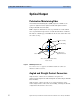
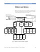
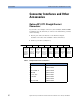
Figure 7 Angled and Straight Contact Connector Symbols
Figure 7 shows the symbols that tell you whether the contact
connector of your Tunable Laser module is angled or straight. The
angled contact connector symbol is colored green.
You should connect straight contact fiber end connectors with neutral
sleeves to straight contact connectors and connect angled contact fiber
end connectors with green sleeves to angled contact connectors.
NOTE You cannot connect angled non-contact fiber end connectors with
orange sleeves directly to the instrument.
See “Accessories” on page 25 for further details on connector
interfaces and accessories.
Signal Input and Output
CAUTION There is one BNC input connector on the front panel of the
Agilent 81689A, Agilent 81689B and Agilent 81649A Compact Tunable
Laser modules
An absolute maximum of ± 6 V can be applied as an external voltage to
any BNC connector.
Straight Contact
Connector Symbol
Angled Contact
Connector Symbol