
User`s guide


The Return Loss Module Getting Started with Return Loss
Agilent 81610A/11A/12A/13A/14A Return Loss Module, Fifth Edition 15
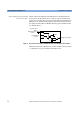
A Description of the Front Panel
Figure 4 Front Panel of Agilent 816010A/11A/12A/13A/14A Return Loss Modules
Inserting the module The procedure for inserting a module into your mainframe is
described in your mainframe’s User’s Guide.
Optical Output
Agilent 8161x series Return Loss modules are equipped with angled
(8
°
) contact optical input and output connectors.
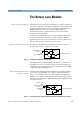
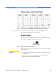
Figure 5 Angled Contact Connector Symbols
Figure 5 shows the symbol for angled contact connectors. This symbol
is colored green.
CAUTION • In order to obtain reliable return loss values connectors must be in
good condition.
• Damage to connectors is not included in the warranty for the
Agilent 8161x series Return Loss modules
Angled Contact
Connector Symbol