
User`s guide


Calibration Measurements Getting Started with Return Loss
Agilent 81610A/11A/12A/13A/14A Return Loss Module, Fifth Edition 19
Calibration Measurements
Before measuring the reflection factor of a device under test (DUT),
take calibration measurements as described in “Calibrating the Return
Loss Module” on page 21. These calibrations eliminate wavelength
dependencies, coupler directivity, insertion losses, backscattering and
other non-ideal characteristics of the system.
Making a Return Loss
Measurement
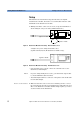
Connectors The Return Loss measurement setup described uses Diamond HMS-
10/Agilent/HRL and Diamond HMS-10/Agilent connectors throughout.
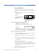
Patchcord on RL module Output It is recommended that you attach a patchcord with a high return loss
connector to the Return Loss module output.
CAUTION Agilent Technologies supplies patchcords with a Diamond HMS-
10/Agilent/HRL high return loss connector on one end. These
patchcords are necessary so that the connector at the output is not
damaged. The full range of patchcords available are described in Table
2.
Table 2 High Return-Loss Patchcords
Model No. High Return-Loss Patchcords
Description
Agilent 81113EC DIN47256/4108 (angled) - Radiall EC
Agilent 81113PC DIN47256/4108 (angled) - FC/PC
Agilent 81113SC DIN47256/4108 (angled) - DIN47256/4108 (angled)
Agilent 81113BC DIN47256/4108 (angled) - Bare Fiber