
User`s guide


Getting Started with Return Loss Making a Return Loss Measurement
20 Agilent 81610A/11A/12A/13A/14A Return Loss Module, Fifth Edition
Setup
The Return Loss measurement setup described uses an Agilent
81654A Source module, inserted as a second module in the the same
mainframe as the Return Loss module.
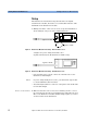
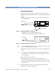
1 Making sure all the connectors are clean, set up the instrument as
shown in Figure 8 if you are using an External Source,
Figure 8 Return Loss Measurement Setup - External Source used
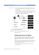
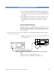
or Figure 9 if you are using an internal source
(Agilent 81611A/2A/3A/4A Return Loss modules only).
Figure 9 Return Loss Measurement Setup - Internal Source used
• If an external source is used, connect the external source to the
Return Loss module Input.
NOTE If you are using a Fabry-Perot source, you must fix its output cable
to ensure minimum cable movement.
• Attach the high return loss connector of the patchcord to the Return
Loss module Output.
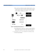
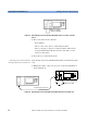
Remove electrical offsets 2 Make sure that the source is not active and that you have covered
the end of the patchcord to prevent light being coupled into the end.
Move to the Return Loss module channel and press [Zero] to remove
electrical offsets in the instrument.
Agilent 81113PC
8161x 8163A Lightwave MultimeterLaser
Source
Agilent 81113PC
8161x
8163A Lightwave Multimeter
Agilent 81109AC
8161x
8163A Lightwave Multimeter