
User`s guide


Making a Return Loss Measurement Getting Started with Return Loss
Agilent 81610A/11A/12A/13A/14A Return Loss Module, Fifth Edition 31
How to Measure Return Loss
It is not necessary to make new calibration measurements for each
DUT. You can make the calibration measurements for your system,
and then measure the return loss of many devices.
The value shown in the result field for the Return Loss channel is the
measured return loss.
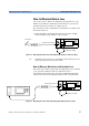
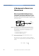
1 Attach the DUT to the measurement patchcord. In the example
shown in Figure 24, the DUT is a connector pair.
Figure 24 Measuring the Return Loss of the DUT (in this example: a Connector Pair)
TIP Terminate your system close to the DUT to make sure that you are
only measuring reflections from the DUT.
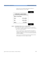
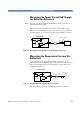
How to Measure Return Loss and Insertion Loss
The return loss module together with an additional power head allow
you to perform combined return loss and insertion loss
measurements. The figure below shows the standard measurement
setup for the reference measurement and the device measurement.
Figure 25 Measuring the Power Transmitted through the DUT (a Connector Pair)
Termination
measurement patchcord
8161x 8163A Lightwave MultimeterLaser
Source
Agilent 81113PC
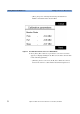
Power
Sensor
8163A Lightwave Multimeter
measurement patchcord
8161x 8163A Lightwave MultimeterLaser
Source
Agilent 81113PC