
User`s guide


Getting Started with Return Loss Making a Return Loss Measurement
32 Agilent 81610A/11A/12A/13A/14A Return Loss Module, Fifth Edition
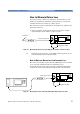
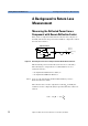
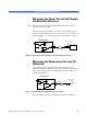
Measuring the Insertion Loss To measure insertion loss, you measure the power transmitted
through the DUT, as shown in Figure 25.
As you have already, in Step 2 on page 28, set the [Ref] parameter to
the power transmitted through the Reference Cable. The displayed
power in dB is equal to the insertion loss.
NOTE Set the Front Panel Delta as described on “Front Panel Delta
Calibration” on page 27.
Viewing the Calibration Values
The Return Loss module calibration values used are either the most
recently measured, where these are available, or factory default
values.
If you are unsure of the calibration values you are using, or if you have
changed your measurement setup, make the appropriate calibration
measurements again.
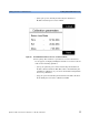
1 Press [Menu]. Move to the <Show calibration> menu item. The
Calibration parameters screen for the Return Loss Diode appears,
as displayed in Figure 26. This screen shows current value for the
following quantities:
–[Para], the parasitic power value measured by the Return loss
Module’s internal power sensor in dBm. This value is determined
by the termination calibration, or you can use the default setting
held in the factory calibration.
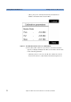
–[Ref], the power measured by the Return loss Module’s internal
power sensor during the reflectance calibration in dBm