
User`s guide


Performance Tests Performance Test Instructions
68 Agilent 81610A/11A/12A/13A/14A Return Loss Module, Fifth Edition
Agilent 81610A/11A/12A/13A/14A:
Relative Uncertainty of Return Loss and
Dynamic Range
The maximum return loss range at the Return Loss Meter is
significantly affected by all parasitic reflections and backscatter
returned to the optical output of the Return Loss Meter.
To minimize these effects, it is essential to use clean connectors, and
to minimize the fiber lengths and the number of optical connections
used in the measurement setup.
1 Make sure that all connectors are clean.
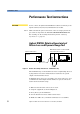
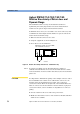
2 Setup the equipment as shown in Figure 39.
3 Press [Preset] on the mainframe.
Figure 39 Relative Uncertainty of Return Loss - Calibration Setup
NOTE To ensure traceability, use the 81610CC Reference Cable for
calibration measurements. Do not use the 81610CC Reference Cable
for measurements on a Device Under Test. Instead, use a measurement
patchcord.
CAUTION It is important to maintain the quality of the straight connector end of
the 81610CC Reference Cable. Never add another connector to the
straight end of the 81610CC Reference Cable, since a physical
connection is made. When the straight end of the 81610CC Reference
Cable is connected to the 81634A Power Sensor module, no physical
connection is made, so there should be no degradation of connector
quality.
4 Zero the return loss meter as well as the power meter.
5 Enable the internal laser source of the return loss module and allow
20min for it to stabilize.
Mainframe 8163A w/ 8161xA RTL
and 81634A Power Sensor
8163A
8161xA
in
out
81634A
81610CC