
User`s guide


Performance Tests Performance Test Instructions
70 Agilent 81610A/11A/12A/13A/14A Return Loss Module, Fifth Edition
b Set ’Wavelength’ to the wavelength of the RTL source.
c Enable the attenuator.
12 At the Return Loss meter, press [TermCal] in order to calibrate the
Return Loss module at termination condition.
13 At the optical attenuator, set the ’Attenuation’ to 0.0dB.The
measured Return Loss should now be identical to the RLref value
entered at step 7.b).
14 Note this return loss value in the Test Record.
15 At the powermeter press [Disp®Ref]. The Power meter should now
read 0.0dB.
16 At the optical attenuator, increase the 'Attenuation' setting until the
Return Loss reading matches the next value in the Test Record.
Note the value on the power meter in the Test Record as 'Actual
Powermeter Reading'.
17 Repeat step 15) and 16) each value in the test record.
18 Now, determine once the maximum polarization uncertainty for this
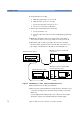
setup. Connect the equipment as shown in figure D-5.
Figure 41 Relative Uncertainty of Polarization
19 Adjust the attenuation of the attenuator until the displayed return
loss value is about 25dB.
20 At the polarization controller:
a Set the scan rate to 3
b Press the 'autoscan' button to start scrambling the polarization.
Mainframe 8163A w/ 8161xA RTL
and 81634A Power Sensor
8163A
8161xA
in
out
81634A
Optical Attenuator 8156A
8156A special
pigtailed
fiber
pigtailed version
Polarization Controller
11896A
fiber
pigtail
1005-0256