Agilent 83438A Erbium ASE Source User’s Guide
© Copyright 2000 Agilent Technologies All Rights Reserved. Reproduction, adaptation, or translation without prior written permission is prohibited, except as allowed under copyright laws. Agilent Part No. 83438-90010 Printed in USA February 2000 Agilent Technologies Lightwave Division 1400 Fountaingrove Parkway Santa Rosa, CA 95403-1799, USA (707) 577-1400 Notice. The information contained in this document is subject to change without notice.
The Agilent 83438A—At a Glance The Agilent 83438A—At a Glance The Agilent 83438A Erbium ASE Source provides incoherent light for characterizing fiber-optic components. Its output is centered at approximately 1550 nm. Because it has a relatively high-power spectral density, you can probe devices with medium or high insertion loss. Its single-mode output originates from the amplified spontaneous emission (ASE) of an Erbium doped fiber amplifier.
The Agilent 83438A—At a Glance The output can be modulated or turned off You can digitally modulate the output using a TTL compatible signal. For a complete discussion of modulating the output light and making measurements with your Agilent 83438A, refer to Chapter 2, “Making Measurements”. Measurement accuracy—it’s up to you! Fiber-optic connectors are easily damaged when connected to dirty or damaged cables and accessories. The Agilent 83438A’s front-panel OPTICAL OUT connector is no exception.
The Agilent 83438A—At a Glance Rear view of instrument v
General Safety Considerations General Safety Considerations This product has been designed and tested in accordance with IEC Publication 61010-1, Safety Requirements for Electrical Equipment for Measurement, Control and Laboratory Use, and has been supplied in a safe condition. The instruction documentation contains information and warnings that must be followed by the user to ensure safe operation and to maintain the product in a safe condition.
General Safety Considerations CAUTION Before switching on this instrument, make sure that the line voltage selector switch is set to the line voltage of the power supply and the correct fuse is installed. Assure the supply voltage is in the specified range. CAUTION This product is designed for use in Installation Category II and Pollution Degree 2 per IEC 1010 and 664 respectively.
Contents The Agilent 83438A—At a Glance iii 1 Getting Started Step 1. Inspect the Shipment 1-4 Step 2. Check the Fuse 1-5 Step 3. Connect the Line-Power Cable 1-6 Step 4.
1 Step 1. Inspect the Shipment 1-4 Step 2. Check the Fuse 1-5 Step 3. Connect the Line-Power Cable 1-6 Step 4.
Getting Started Getting Started Getting Started The instructions in this chapter show you how to install your Agilent 83438A. You should be able to finish these procedures in about ten to twenty minutes. After you’ve completed this chapter, continue with Chapter 2, “Making Measurements”. Refer to Chapter 3, “Specifications and Regulatory Information” for information on operating conditions such as temperature. If you should ever need to clean the cabinet, use a damp cloth only.
Getting Started Getting Started Measurement accuracy—it’s up to you! Fiber-optic connectors are easily damaged when connected to dirty or damaged cables and accessories. The Agilent 83438A’s front-panel OPTICAL OUT connector is no exception. When you use improper cleaning and handling techniques, you risk expensive instrument repairs, damaged cables, and compromised measurements.
Getting Started Step 1. Inspect the Shipment Step 1. Inspect the Shipment 1 Verify that all components ordered have arrived by comparing the shipping forms to the original purchase order. Inspect all shipping containers. If your shipment is damaged or incomplete, save the packing materials and notify both the shipping carrier and the nearest Agilent Technologies service office.
Getting Started Step 2. Check the Fuse Step 2. Check the Fuse 1 Locate the line-input connector on the instrument’s rear panel. 2 Disconnect the line-power cable if it is connected. 3 Use a small flat-blade screwdriver to open the pull-out fuse drawer. 4 Verify that the value of the line-voltage fuse in the pull-out drawer is correct. The recommended fuse is an IEC 127 5×20 mm, 6.3A, 250 V, Agilent part number 2110-0703. Notice that an extra fuse is provided in a drawer located on the fuse holder.
Getting Started Step 3. Connect the Line-Power Cable Step 3. Connect the Line-Power Cable CAUTION Always use the three-prong AC power cord supplied with this instrument. Failure to ensure adequate earth grounding by not using this cord may cause instrument damage. CAUTION Do not connect ac power until you have verified the line voltage is correct as described in the following paragraphs. Damage to the equipment could result. CAUTION This instrument has autoranging line voltage input.
Getting Started Step 4. Turn on the Agilent 83438A Step 4. Turn on the Agilent 83438A 1 Press the front-panel LINE key. The front-panel LINE switch disconnects the mains circuits from the mains supply after the EMC filters and before other parts of the instrument. 2 Use the front-panel ACTIVE key to turn the light output on and off.
Getting Started Returning the Instrument for Service Returning the Instrument for Service The instructions in this section show you how to properly return the instrument for repair or calibration. Always call the Agilent Technologies Instrument Support Center first to initiate service before returning your instrument to a service office. This ensures that the repair (or calibration) can be properly tracked and that your instrument will be returned to you as quickly as possible.
Getting Started Returning the Instrument for Service information should be returned with the instrument. • Type of service required. • Date instrument was returned for repair. • Description of the problem: • Whether problem is constant or intermittent. • Whether instrument is temperature-sensitive. • Whether instrument is vibration-sensitive. • Instrument settings required to reproduce the problem. • Performance data. • Company name and return address. • Name and phone number of technical contact person.
Getting Started Returning the Instrument for Service Sealed Air Corporation (Commerce, California 90001). Air Cap looks like a plastic sheet filled with air bubbles. Use the pink (antistatic) Air Cap™ to reduce static electricity. Wrapping the instrument several times in this material will protect the instrument and prevent it from moving in the carton. 4 Seal the carton with strong nylon adhesive tape. 5 Mark the carton “FRAGILE, HANDLE WITH CARE”. 6 Retain copies of all shipping papers.
2 Performing Stimulus-Response Measurements 2-3 To characterize a passive device 2-5 Ambient Light Suppression 2-7 To suppress ambient light 2-8 Modulating the Output Light 2-10 Cleaning Connections for Accurate Measurements 2-11 Making Measurements
Making Measurements Making Measurements Making Measurements In this chapter, you’ll find examples of making measurements using the Agilent 83438A. These examples use your Agilent 83438A in conjunction with an Agilent 71450/1/2B optical spectrum analyzer. This combination provides up to 70 dB of measurement range.
Making Measurements Performing Stimulus-Response Measurements Performing Stimulus-Response Measurements This section shows you how to perform stimulus-response measurements.
Making Measurements Performing Stimulus-Response Measurements 2-4
Making Measurements Performing Stimulus-Response Measurements To characterize a passive device 1 Turn on the optical spectrum analyzer and the Agilent 83438A, and allow them to warm up for 1 hour. 2 Use a fiber optic cable to connect the Agilent 83438A’s output to the input of the optical spectrum analyzer. 3 On the optical spectrum analyzer, press INSTR PRESET, AUTO MEAS, and then AUTO ALIGN. 4 On the optical spectrum analyzer, use the START and STOP keys to set the proper wavelength range.
Making Measurements Performing Stimulus-Response Measurements If changes to wavelength range or resolution bandwidth are made after this trace is stored, repeat this step. 10 Insert the device you are testing between the optical spectrum analyzer and the Agilent 83438A. 11 Press NORMAL ON/OFF to turn the marker on. Rotate the front-panel knob to read the values along the response.
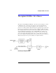
Making Measurements Ambient Light Suppression Ambient Light Suppression Ambient light can add significant errors to optical power measurements. This is especially true when you are using or characterizing open beam devices. The following example shows how the combination of the Agilent 83438A and an Agilent 71450/1/2B optical spectrum analyzer can be used to eliminate this error. In order to perform this measurement, the Agilent 83438A’s output is modulated at 270 Hz.
Making Measurements Ambient Light Suppression To suppress ambient light This example uses specific equipment and settings to demonstrate how to make accurate measurements in the presence of ambient light. As shown in the equipment setup drawing, two Agilent 83438As are used. One Agilent 83438A represents the broadband contribution of ambient light. Because a 12 dB coupler is used, the ambient light contributes approximately 10 dB more power to the optical spectrum analyzer than the desired source.
Making Measurements Ambient Light Suppression 5 Press REF LEVEL, and set the reference level to –10 dBm. 6 Press Amptd, LOG dB/DIV, and enter 5 dB. 7 Press MORE, CHOP On Off so that Off is underlined. 8 Press BW,Swp, SWPTIME AutoMan, and set the sweep time to 10 seconds. 9 Press MORE, MORE, adc trigger, and then ADCTRIG AC. 10 Press ADCTRIG DELAY, and enter a value of 1 ms. 11 The display should now show the proper amplitude values with the effect of the ambient light subtracted out.
Making Measurements Modulating the Output Light Modulating the Output Light The rear panel of the instrument is equipped with a MODULATION INPUT connector. You can use this connector to digitally modulate the source for applications using lock-in techniques. (Refer to “Ambient Light Suppression” on page 2-7.) Or, you can completely disable its output light. Digital modulation requires a TTL compatible signal. Modulation rates can range from DC to 300 Hz. A “high” TTL value turns the source on.
Making Measurements Cleaning Connections for Accurate Measurements Cleaning Connections for Accurate Measurements Today, advances in measurement capabilities make connectors and connection techniques more important than ever. Damage to the connectors on calibration and verification devices, test ports, cables, and other devices can degrade measurement accuracy and damage instruments.
Making Measurements Cleaning Connections for Accurate Measurements tions take repeatability uncertainty into account? • Will a connector degrade the return loss too much, or will a fusion splice be required? For example, many DFB lasers cannot operate with reflections from connectors. Often as much as 90 dB isolation is needed. Figure 2-1. Basic components of a connector. Over the last few years, the FC/PC style connector has emerged as the most popular connector for fiber-optic applications.
Making Measurements Cleaning Connections for Accurate Measurements Figure 2-2. Universal adapters to Diamond HMS-10. The HMS-10 encases the fiber within a soft nickel silver (Cu/Ni/Zn) center which is surrounded by a tough tungsten carbide casing, as shown in Figure 2-3. Figure 2-3. Cross-section of the Diamond HMS-10 connector. The nickel silver allows an active centering process that permits the glass fiber to be moved to the desired position.
Making Measurements Cleaning Connections for Accurate Measurements The soft core, while allowing precise centering, is also the chief liability of the connector. The soft material is easily damaged. Care must be taken to minimize excessive scratching and wear. While minor wear is not a problem if the glass face is not affected, scratches or grit can cause the glass fiber to move out of alignment. Also, if unkeyed connectors are used, the nickel silver can be pushed onto the glass surface.
Making Measurements Cleaning Connections for Accurate Measurements Use the following guidelines to achieve the best possible performance when making measurements on a fiber-optic system: • Never use metal or sharp objects to clean a connector and never scrape the connector. • Avoid matching gel and oils. Figure 2-4. Clean, problem-free fiber end and ferrule. Figure 2-5. Dirty fiber end and ferrule from poor cleaning.
Making Measurements Cleaning Connections for Accurate Measurements Figure 2-6. Damage from improper cleaning. While these often work well on first insertion, they are great dirt magnets. The oil or gel grabs and holds grit that is then ground into the end of the fiber. Also, some early gels were designed for use with the FC, non-contacting connectors, using small glass spheres. When used with contacting connectors, these glass balls can scratch and pit the fiber.
Making Measurements Cleaning Connections for Accurate Measurements • Keep connectors covered when not in use. • Use fusion splices on the more permanent critical nodes. Choose the best connector possible. Replace connecting cables regularly. Frequently measure the return loss of the connector to check for degradation, and clean every connector, every time. All connectors should be treated like the high-quality lens of a good camera.
Making Measurements Cleaning Connections for Accurate Measurements Visual inspection of fiber ends Visual inspection of fiber ends can be helpful. Contamination or imperfections on the cable end face can be detected as well as cracks or chips in the fiber itself. Use a microscope (100X to 200X magnification) to inspect the entire end face for contamination, raised metal, or dents in the metal as well as any other imperfections. Inspect the fiber for cracks and chips.
Making Measurements Cleaning Connections for Accurate Measurements Table 2-2. Dust Caps Provided with Lightwave Instruments Item Agilent Part Number Laser shutter cap 08145-64521 FC/PC dust cap 08154-44102 Biconic dust cap 08154-44105 DIN dust cap 5040-9364 HMS10/dust cap 5040-9361 ST dust cap 5040-9366 To clean a non-lensed connector CAUTION Do not use any type of foam swab to clean optical fiber ends. Foam swabs can leave filmy deposits on fiber ends that can degrade performance.
Making Measurements Cleaning Connections for Accurate Measurements CAUTION Do not shake, tip, or invert compressed air canisters, because this releases particles in the can into the air. Refer to instructions provided on the compressed air canister. 7 As soon as the connector is dry, connect or cover it for later use. If the performance, after the initial cleaning, seems poor try cleaning the connector again. Often a second cleaning will restore proper performance.
3 Specifications 3-3 Regulatory Information 3-6 Specifications and Regulatory Information
Specifications and Regulatory Information Specifications and Regulatory Information Specifications and Regulatory Information This chapter lists specification and characteristics of the instrument. The distinction between these terms is described as follows: • Specifications describe warranted performance over the temperature range 0°C to +45°C and relative humidity <95% (unless otherwise noted).
Specifications and Regulatory Information Specifications Specifications General Specifications Total output powera +8.1 dBm maximum (6.5 mW) +5.5 dBm minimum (3.5 mW) +5.1 dBm maximum (3.2 mW) (Option 009) +2.5 dBm minimum (1.8 mW) (Option 009) Power stabilityb < ±0.02 dB (15 minutes) < ±0.05 dB (6 hours) Compatible fiber 9/125 µm, single mode a. Measured with an InGaAs power sensor. b.
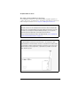
Specifications and Regulatory Information Specifications Characteristic output spectrum (1500 nm to 1600 nm) Characteristic output spectrum (1550 nm to 1560 nm) 3-4
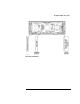
Specifications and Regulatory Information Specifications Characteristic output waveform when modulated with 270 Hz square wave Operating Specifications Use Power: Voltage Frequency Altitude Operating temperature Indoor 115 VAC: 50 WATTS MAX. 230 VAC: 50 WATTS MAX.
Specifications and Regulatory Information Regulatory Information Regulatory Information • Laser Classification: This product contains an IEC LASER Class 1. • This product complies with 21 CFR 1040.10 Class 1, IEC 825-1 Class 1. • This product is designed for use in INSTALLATION CATEGORY II and POLLUTION DEGREE 2, per IEC 1010 and 664 respectively.
Specifications and Regulatory Information Regulatory Information Declaration of Conformity I’ll 3-7
4 Instrument Options 4-2 Accessories 4-2 Front-Panel Fiber-Optic Adapters 4-3 Power Cords 4-4 Agilent Technologies Service Offices 4-5 Reference
Reference Instrument Options Instrument Options Option Description 009 Built-in polarizer 011 Diamond HMS-10 fiber-optic input connector interface 013 DIN 47256 fiber-optic input connector interface 014 ST fiber-optic input connector interface 017 SC fiber-optic input connector interface 022 Angled contact fiber-optic output interface Accessories • BNC short (m) for rear-panel MODULATION INPUT connectors. Disables selected source. Agilent Technologies part number 1250-0774.
Reference Front-Panel Fiber-Optic Adapters Front-Panel Fiber-Optic Adapters Front Panel Fiber-Optic Adapter Description Agilent Part Number Diamond HMS-10 81000AI FC/PCa 81000FI D4 81000GI SC 81000KI DIN 81000SI ST 81000VI Biconic 81000WI Dust Covers FC connector 1005-0594 Diamond HMS-10 connector 1005-0593 DIN connector 1005-0595 ST connector 1005-0596 SC connector 1005-0597 a. The FC/PC adapter is the standard adapter supplied with the instrument.
Reference Power Cords Power Cords Plug Type Cable Part No.
Reference Agilent Technologies Service Offices Agilent Technologies Service Offices Before returning an instrument for service, call the Agilent Technologies Instrument Support Center at (800) 403-0801, visit the Test and Measurement Web Sites by Country page at http://www.tm.agilent.com/tmo/country/English/ index.html, or call one of the numbers listed below. Agilent Technologies Service Numbers Austria 01/25125-7171 Belgium 32-2-778.37.
5 General Information 5-4 Electrostatic Discharge Information 5-10 Troubleshooting 5-12 If the output power is low 5-14 To check the A5 Laser Driver Board Assembly 5-15 To check the A2A2 Laser Modulation Board Assembly 5-17 To check the A4 Power Supply Board Assembly 5-18 To check the line-power fuse 5-19 Performance Tests 5-20 Test 1. Total Output Power 5-21 Test 2.
Servicing Servicing Servicing In this chapter, you'll find information on troubleshooting, testing performance, adjusting, and replacing parts in the instrument. Safety first! Before servicing the Agilent 83438A, familiarize yourself with the safety markings on the instrument and the safety instructions in this manual. This instrument has been manufactured and tested according to international safety standards.
Servicing Servicing WARNING For continued protection against fire hazard, replace line fuse only with same type and ratings, (type T 6.3A/250V for 100/240V operation). The use of other fuses or materials is prohibited. WARNING Use of controls or adjustment or performance of procedures other than those specified herein may result in hazardous radiation exposure.
Servicing General Information General Information Whenever you contact Agilent Technologies about your Agilent 83438A, have the complete serial number and option designation available. This will ensure you obtain accurate service information. • Refer to Table 5-1 on page 5-5 for a list of internal labels. • Refer to Table 5-2 on page 5-6 for a list of service tools. • Refer to Table 5-3 on page 5-6 for the location of each instrument assembly.
Servicing General Information WARNING To avoid exposure to the laser path of a CLASS IIIb LASER PRODUCT, do not open the A2A1 assembly. There are no serviceable components inside. Do not damage the fiber-optic cable that connects the CLASS IIIb pump laser, A2A3, to the A2A1 assembly. Other laser paths outside of the A2A1 assembly do not require precautions to maintain safety. Table 5-1.
Servicing General Information Table 5-2. Service Tools Tool Agilent Part Number Small Pozidriv screwdriver 8710-0899 Wire cutter 8710-0012 Long-nose pliers 8710-1107 5.5 mm nut driver 8710-1220 7 mm nut driver 8710-1217 TORX T-10 driver 8710-1623 TORX T-15 driver 8710-1622 Table 5-3.
Servicing General Information 5-7
Servicing General Information Table 5-4.
Servicing General Information 5-9
Servicing Electrostatic Discharge Information Electrostatic Discharge Information Electrostatic discharge (ESD) can damage or destroy electronic components. All work on electronic assemblies should be performed at a static-safe work station. The following figure shows an example of a static-safe work station using two types of ESD protection: • Conductive table-mat and wrist-strap combination. • Conductive floor-mat and heel-strap combination.
Servicing Electrostatic Discharge Information To ensure user safety, the static-safe accessories must provide at least 1 MΩ of isolation from ground. Refer to Table 5-5 on page 5-11 for information on ordering static-safe accessories. WARNING These techniques for a static-safe work station should not be used when working on circuitry with a voltage potential greater than 500 volts. Table 5-5. Static-Safe Accessories Agilent Part Number Description 9300-0797 3M static control mat 0.6 m × 1.
Servicing Troubleshooting Troubleshooting The following procedures are located in this section: If the output power is low 5-14 To check the A5 Laser Driver Board Assembly 5-15 To check the A2A2 Laser Modulation Board Assembly 5-17 To check the A4 Power Supply Board Assembly 5-18 To check the line-power fuse 5-19 WARNING To avoid exposure to the laser path of a CLASS IIIb LASER PRODUCT, do not open the A2A1 assembly. There are no serviceable components inside.
Servicing Troubleshooting WARNING The opening of covers or removal of parts is likely to expose dangerous voltages. Disconnect the instrument from all voltage sources while it is being opened. WARNING The power cord is connected to internal capacitors that may remain live for five seconds after disconnecting the plug from its power supply.
Servicing Troubleshooting If the output power is low 1 Check for the following common problems: ❒ Check that the front-panel ACTIVE key is on. If the ACTIVE or LINE LEDs do not light, refer to “To check the A4 Power Supply Board Assembly” on page 5-18. ❒ Clean the OPTICAL OUT connector as described in “Cleaning Connections for Accurate Measurements” on page 2-11. ❒ Remove any modulating signal from the rear-panel MODULATION INPUT connector. Modulation reduces the average output power.
Servicing Troubleshooting To check the A5 Laser Driver Board Assembly If the A5 Laser Driver Board Assembly needs to be replaced, perform the instructions in “To replace the A5 Laser Driver Board Assembly” on page 5-30. New A5 assemblies are shipped with three resistors unloaded. You must match the values of these resistors to the values loaded in the original A5 assembly. A bag of resistors is supplied with the new assembly.
Servicing Troubleshooting 3 If the green LED is on, the current source driving the pump laser is operating correctly. If the yellow LED is on, the pump laser’s temperature stabilization loop is not functioning; the current to the pump laser is automatically turned off which turns the green LED off. 4 If the yellow LED is off, check ribbon cable W12.
Servicing Troubleshooting To check the A2A2 Laser Modulation Board Assembly 1 Check the +5V supply by probing the center pin of J11. The modulation input cable from the rear panel connects to this jack. 2 Check the –15V supply by probing any of the three resistors that are located next to J2. These resistors are loaded in a straight line and have the label “1471” printed on them. 3 Locate the large 3W black resistor on the assembly that is closest to the pump laser.
Servicing Troubleshooting To check the A4 Power Supply Board Assembly 1 Check the 6.3A fuse in the rear-panel’s line module FL1. Refer to “To check the line-power fuse” on page 5-19. 2 Remove the power supply cable from J2 on the A5 Laser Driver Board Assembly. The end of this cable can be probed to measure all of the dc voltages supplied in the instrument.
Servicing Troubleshooting To check the line-power fuse 1 Locate the line-input connector on the instrument’s rear panel. 2 Disconnect the line-power cable if it is connected. 3 Use a small flat-blade screwdriver to open the pull-out fuse drawer. The recommended fuse is an IEC 127 5×20 mm, 6.3A, 250 V, Agilent Technologies part number 2110-0703. Notice that an extra fuse is provided in a drawer located on the fuse holder.
Servicing Performance Tests Performance Tests The procedures in this section test the Agilent 83438A’s performance using the specifications listed in Chapter 3, “Specifications and Regulatory Information” as the performance standard. All of the tests are done manually without the aid of a computer. None of these tests require access to the interior of the instrument. Allow the Agilent 83438A to warm up for 15 minutes before doing any of the performance tests. Test 1. Total Output Power 5-21 Test 2.
Servicing Performance Tests Test 1. Total Output Power Description Total power is verified using the following devices: • Power meter Procedure 1 Connect a power meter to the Agilent 83438A’s front-panel OPTICAL OUT connector. 2 Measure the total power.
Servicing Performance Tests Test 2. Power Stability Description Power stability is verified using a power meter (> 30 dB return loss) This test must be performed in a stable environment where the ambient temperature changes less than 1°C throughout the test. Procedure 1 Turn on the Agilent 83438A and the power meter. Allow them to warm up for one hour. 2 Connect a power meter to the Agilent 83438A’s front-panel OPTICAL OUT connector.
Servicing Adjustment Procedure Adjustment Procedure The Agilent 83438A has only one adjustment procedure, total power. Periodic adjustment is not required to maintain safety. CAUTION Option 022 instruments have an angled-fiber output. Be sure to use an angledfiber patchcord during testing. If you do not have an angled-fiber patchcord available, you can purchase the required accessories from Agilent Technologies.
Servicing Adjustment Procedure To adjust total power Description The total power is adjusted by a potentiometer. The potentiometer is located on the A5 Laser Driver Board Assembly. Procedure 1 Remove the instrument’s top and bottom covers. 2 Connect a power meter to the Agilent 83438A’s front-panel OPTICAL OUT connector. 3 Locate R18 on the A5 Laser driver board assembly for the pump laser. See the following figure.
Servicing Adjustment Procedure 5-25
Servicing Replacing Instrument Assemblies Replacing Instrument Assemblies This section provides step-by-step procedures to remove and replace the major instrument assemblies.
Servicing Replacing Instrument Assemblies To remove the instrument cover 1 Disconnect the power cord from the instrument. 2 Position the instrument so that you are looking at the rear panel. 3 Use a T-15 TORX driver to back out the screw that attaches the top cover to the instrument. Note that the screw is permanently secured to the cover. 4 After the screw is backed out, slide the cover toward the rear of the instrument to remove it.
Servicing Replacing Instrument Assemblies To replace the A2 Source assembly The A2 assembly, which includes A2A1, A2A2, A2A3, A2MP1, and A2MP2, must be replaced as a complete unit. Individual components cannot be repaired. WARNING To avoid exposure to the laser path of a CLASS IIIb LASER PRODUCT, do not open the A2A1 assembly. There are no serviceable components inside. Do not damage the fiber-optic cable that connects the CLASS IIIb pump laser, A2A3, to the A2A1 assembly.
Servicing Replacing Instrument Assemblies 6 Be sure to cover the exposed end of the fiber-optic cable. 7 Use a T-10 TORX driver to remove the four screws securing the A2 assembly to the instrument’s right-side frame. 8 Place the instrument on it’s right side. 9 Use a T-10 TORX driver to remove the three screws securing the A2 assembly to the bottom of the instrument’s main deck sheet metal assembly. 10 Remove the A2 assembly.
Servicing Replacing Instrument Assemblies To replace the A5 Laser Driver Board Assembly Three resistors on the A5 Laser Driver Board Assembly limit the maximum current to the A2A3 Pump Laser. These resistors are matched to the particular pump laser installed in your instrument. New A5 assemblies are shipped with these three resistors unloaded. You must load new resistors, which match the values loaded in the original A5 assembly, into the new A5 assembly.
Servicing Replacing Instrument Assemblies Location of resistors R2, R8, and R9 5-31
Servicing Replacing Instrument Assemblies To route the rear-panel BNC modulation cable The figure below shows the correct path for the rear-panel BNC cable. Be sure to route this cable as shown.
Servicing Replacing Instrument Assemblies To replace line filter assembly FL1 Although replacing FL1 is straightforward, be sure to observe the following points: • Tighten the screws that attach FL1 to 6 in-lbs. Do not use the recommended torque for M3 screws. Over tightening these screws will damage the line filter’s flange. • Observe the following warning about correct wire attachment.
Servicing Replacing Instrument Assemblies To replace a cable clip Cable clips are used throughout the instrument to attach cables to sheet-metal housings. They attach with self-adhesive bonds. 1 Remove the old clip. 2 Remove any remaining glue. 3 Clean the surface using isopropyl alcohol. 4 Remove the paper backing from the bottom of the new clip. 5 Press the clip firmly onto the surface.
Servicing Replaceable Parts 5Servicing Replaceable Parts In this section, you’ll find figures that identify each mechanical and electrical assembly in the instrument. An Agilent Technologies part number is provided for each available part.
Servicing Replaceable Parts Direct mail-order system Within the USA, Agilent Technologies can supply parts through a direct mailorder system. Advantages of using the system are as follows: • Direct ordering and shipment from Agilent Technologies • No maximum or minimum on any mail order. (There is a minimum order amount for parts ordered through a local Agilent Technologies office when the orders require billing and invoicing.) • Prepaid transportation. (There is a small handling charge for each order.
Servicing Replaceable Parts Table 5-6.
Servicing Replaceable Parts 5-38
Servicing Replaceable Parts Table 5-7.
Servicing Replaceable Parts 5-40
Servicing Replaceable Parts Table 5-8. Front-Panel Parts Item Agilent Part Number Qty Description 1 2 3 4 5 6 7 8 9 10 11 12 13 14 15 83437-00002 5021-8413 83437-00001 54714-41903 1990-1213 85680-40004 83437-20004 83410-20003 0515-0430 0535-0042 1400-0755 1400-0249 0380-0019 0590-0106 3050-0891 1 1 1 1 2 2 1 1 3 3 3 1 2 2 2 Front panel, dress Front frame Front subpanel ACTIVE key LED lamp IF=15 mA maximum LED mount LED spacer Adapter Screw with washer, TORX T10 Pan Head, M3 X 0.
Servicing Replaceable Parts 5-42
Servicing Replaceable Parts Table 5-9. Rear-Panel Parts Item Agilent Part Number Qty Description 1 2 3 4 5 6 7 8 9 10 11 83437-00005 5021-5814 2110-0703 0515-2032 0535-0033 2190-0585 3050-0892 2950-0035 2190-0102 6960-0002 0515-0372 1 1 1 2 4 4 4 4 4 3 4 Rear panel, dress Rear frame Fuse, 6.3A 250V NTD FE IEC Screw, TORX T10 Flat Head, M3 X 0.5, 8 mm long Nut, hex M3.5 X 0.6 Washer, flat HLLC 3.6 mm inside diameter Washer, flat MTLC 3.8 mm inside diameter Nut, hex 15/32-32 Washer, lock 0.
Servicing Replaceable Parts 5-44
Servicing Replaceable Parts Table 5-10. Top and Bottom View Parts Item Agilent Part Number Qty Description Screw, TORX T10 90° Flat Head, M3.5 x 0.6, 8mm long Trim strip, top (not shown) Ribbon cable clip A2MP2, Sheet-metal optical deck (part of A2 assembly) Sheet-metal power supply deck Shield for A4 Power Supply Component clip 0.75 in x 0.
Servicing Replaceable Parts 5-46
Servicing Replaceable Parts Table 5-11. Side View Parts Item Agilent Part Number Qty Description 1 2 3 4 5 6 7 5021-5831 5001-0538 0515-0458 0515-2086 0515-0377 1400-0249 — 2 2 10 8 4 1 5 Side frame Trim strip, side (not shown) Screw, TORX T10 Pan Head, M3.5 x 0.6, 8 mm long Screw, TORX T15 Flat Head, M4 x 0.7, 7 mm long Screw, TORX T10 Pan Head, M3.5 x 0.
Servicing Replaceable Parts Table 5-12.
Index A ac power cables, 1-6, 4-4 accessories, 4-2 accuracy measurement, iv wavelength, 2-3 ACTIVE key, 1-7 adapters fiber optic, 4-3 Agilent offices, 4-5 ambient light, 2-7 angled output fiber, 1-4, 4-2 assemblies, instrument, 5-6, 5-37 cotton swabs, 2-18 crosstalk, 2-3 D damaged shipment, 1-4 declaration of conformity, 3-7 deep-notch filters, 2-3 digital modulation, 2-10 dimensions of instrument, 3-5 dust caps, 2-19 DWDM, 2-3 E B block diagram, iii BNC short, 2-10 broadband stimulus, 2-3 edge emittin
Index installing, 1-2 instrument cover, removing, 5-27 rear view, v returning for service, 1-8 L laser aperture, iv classification, iv, 3-6 laser classification, 3-5 LINE key, 1-7 line-power cable, 1-6, 4-4 cables, 4-4 filter assembly, replacing, 5-33 input connector, 1-5, 5-19 requirements, 1-6 specifications, 3-3, 3-5 M measurement accuracy, 1-3 deep-notch filters, 2-3 DWDM, 2-3 stimulus response, 2-3 modulation, iv, 2-10 frequency, 2-8, 2-10 TTL compatible, 2-10 MODULATION INPUT connector, 2-10 N noi
Index T tools for servicing, 5-4 troubleshooting, 5-2 TTL logic, 2-10 turning output off, 2-10 V ventilation requirements, 1-2 W wavelength accuracy, 2-3 specifications, 3-3 weight, 3-5 Index-3